Atdec TH-31-55-SA-PK Manual

Atdec Ikke kategoriseret TH-31-55-SA-PK

Læs gratis den danske manual til Atdec TH-31-55-SA-PK (2 sider) i kategorien Ikke kategoriseret. Denne vejledning er vurderet som hjælpsom af 27 personer og har en gennemsnitlig bedømmelse på 4.7 stjerner ud af 14 anmeldelser. Har du et spørgsmål om Atdec TH-31-55-SA-PK, eller vil du spørge andre brugere om produktet?

Side 1/2
TM
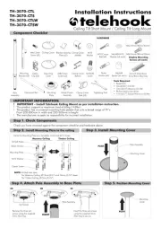
Component Checklist
Due to continuing product development, the manufacturer reserves the right to alter specifications without notice. Published: 24.11.06 c
E Mounting the Display
Installation Instructions
TELEHOOK
31-55 Tilt Wall
31-55” Horizontal Bar
31-55” Bracket (Left)
31-55” Bracket (Right)
Slider (x2)
Hex Tool
5mm
Allen Key
M8 Small
Washer (x2)
Wall Plug (x4)
M8 Large
Washer (x4)
M8 x45mm
Screws (x2)
Multi
Washer (x6)
M5 x 16mm
Screw (x6)
M6 x 16mm
Screw (x6)
M8 x 16mm
Screw (x6)
M8 Coach
Screw (x4)
M4 x 16mm
Screw (x6)
M8 Screw Hole
L
M6 Screw Hole
M5 & M4
Screw Hole
C
Step 2
Use the supplied Multi Washer as shown
above. Ensure that the tightest fitting hole in
the washer is used for the specific sized screw.
Note distance X, for use in the
following steps
X
=
=
=
=
==
Note: This operation may
require two persons.
Now that the horizontal bar is
attached to the wall with the
Sliders in place, lift the Display
with brackets attached and
hook the Brackets over the
Sliders. Let the display rest
against the wall.
Step 1
Fit two M8x45mm locking screws into brackets
behind Display. Adjust the Tilt angle of the
Display. Tighten two locking screws with Hex
Tool provided.
WARNING: Do not attempt to adjust
tilt angle without firstly loosening
locking screws. Doing so may damage
product.
M8 Small
Washer
M8x45mm
Screw
Hex Tool
Tighten
-5° to 10° Tilt
TOP
Step 2
Store the Hex Tool
behind the display
Bit Box
Clinch Nuts
Multi Washer
Step 1
Attach left and right brackets to the rear of your display. Select M4, M5, M6 or M8 fasteners to suit your display. Ensure
a minimum of two fasteners are used per bracket. Clinch nuts must be positioned as shown (internally).
Note: The brackets should
rest on the horizontal bar
with the slider between the
bracket.
For added security you may choose to attach a padlock
to one or both brackets to prevent the theft of the
display. It is recommended that the padlock should
have a shackle diameter of 5mm (
3
/
16
”).
Padlock
5mm (
3
/
16
”)
diameter shackle
NOTE:
The manufacturer does
not accept responsibility
for incorrect installation.
Telehook 31-55 Tilt
Wall supports a
maximum weight of
60kgs (132lbs)
TOOLS REQUIRED:
zPower Drill
z12mm (1/2”) Drill Bit
z8mm (5/16”) Drill Bit
zAdjustable wrench
IMPORTANT:
Ensure you have received all parts against the component checklist prior to installing.
A Attaching the Brackets to the Display
G Security Option
Clinch Nuts
F Fix the Tilt angle of the Display
or
D Attaching the Telehook Tilt Unit to Wall
Depending on the wall fixing configuration chosen in B follow the appropriate instructions;
M8 Coach Screw (x4)
D.1 For Timber Studs Wall fixing.
(Option B.1 A or B)
Step 1
Using the Wall Mounts, mark
the location of the four holes
and drill 40mm (1
1
/
2
”) deep
using a 6mm (
1
/
4
”) timber
drill bit. Use a spirit level
to ensure the top of the
Horizontal Bar is level.
Step 2
Secure the Wall Mounts to
the timber studs by using the
M8 Coach Screws and M8
Large Washers as shown in
the diagram.
M8 Large Washer (x4)
D.2 For Brick & Masonry Wall fixing. (Option B.2)
Step 1
Using the Wall Mounts, mark
the location of the four holes
and drill 70mm (2
3
/
4
”) deep
1
/
2
”) masonry
drill bit. Use a spirit level
to ensure the top of the
Horizontal Bar is level.
Step 2
Secure the Wall Mounts to
the wall using the M8 Coach
Screws, M8 Large Washers
and Wall Plugs as shown in
the diagram.
M8 Coach Screw (x4)
M8 Large Washer (x4)
Wall Plug (x4)
B Select Wall Fixing Configuration - SELECT B1 (A or B) or B2
B.2 Masonry Wall fixing.
It is recommended that the Wall
mount spacing be less than X.
B.1 Timber Stud Wall Fixing
NOTE! FOR PLASTER BOARD WALLS, THE UNIT MUST BE FIXED DIRECTLY TO THE TIMBER STUDS.
Select configuration A or B.
CONFIGURATION A:
Where X is greater than Stud
Spacing.
C Position Wall Mounts and Sliders
Wall Mounts
Step 1
Position wall mounts and sliders as per configuration selected in section B. Accurately position sliders at distance X as recorded
in Section A. Position the wall mount as per your stud spacing distance. Ensure Sliders and Wall Mounts are equally spaced
along the centre Horizontal Bar.
Distance (X)
a
a
b
b
Stud spacing
(for B.1)
Slider
(x2)
Grub
Screws (x4)
X
X
STUD SPACING
STUD SPACING
WALL MOUNT
SPACING
X
Step 2
Secure slider in position
and tighten firmly with
supplied Allen key. Ensure
that it wedges into the slot
on horizontal bar. The
grub screw should tighten
flush to surface.
Step 3
Secure Wall mount in
position and tighten
firmly with supplied Allen
key. Ensure that it wedges
into the slot on horizontal
bar. The grub screw
should tighten flush to
surface.
6mm (
1
/
4
”) x 40mm
(1
1
/
2
“) deep (x4)
12mm (
1
/
2
”) x 70mm
(2
3
/
4
”) deep (x4)
Tighten
Tighten
CONFIGURATION B:
Where Stud Spacing is
greater than X.
L
C


Produkt Specifikationer

Mærke: Atdec
Kategori: Ikke kategoriseret
Model: TH-31-55-SA-PK
Produktfarve: Sort
Panel montering grænseflade: 200 x 100,200 x 200,300 x 200,300 x 300,400 x 300,400 x 400,600 x 400 mm
Monteringstype: Væg
Hældningsvinkelområde: -5 - 25 °
Maksimal vægtkapacitet: 65 kg
Maksimal skærmstørrelse kompatibilitet: 22 "
Minimal skærmstørrelse kompatibilitet: - "
Montering interface kompatibilitet (min.): 200 x 100 mm
Montering interface kompatibilitet (maks.): 600 x 400 mm
Maksimal afstand til gulv: 101.6 mm

Har du brug for hjælp?

Hvis du har brug for hjælp til Atdec TH-31-55-SA-PK stil et spørgsmål nedenfor, og andre brugere vil svare dig


Ikke kategoriseret Atdec Manualer
Ikke kategoriseret Manualer

Nyeste Ikke kategoriseret Manualer

Elektrobock

Elektrobock PT44 Manual

14 September 2025
BSS Audio

BSS Audio FDS-366T Manual

14 September 2025
Systemair

Systemair Airline R-114 Manual

14 September 2025
IFM

IFM SU2031 Manual

14 September 2025
IMC Networks

IMC Networks 232CL9R Manual

14 September 2025
Melissa & Doug

Melissa & Doug 9336 Manual

14 September 2025
Opus

Opus dataPREDATOR Manual

13 September 2025