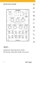
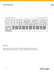
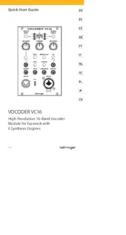
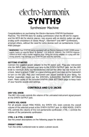
Quick Start Guide
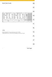
(EN) Controls
(1) EXT SIG X/NOISE jack routes audio signals or noise into the
ring modulator. The audio signal or noise coming in through
the EXT SIG X/NOISE jack is combined with and modulated
by the carrier signal routed into the EXT SIG Y/LFO jack.
(2) EXT SIG Y/LFO jack routes the carrier signal into the
ring modulator. The carrier signal can be in the audio
range, such as a 500 Hz sine wave, or a signal from
Low Frequency Oscillator (LFO).
(3) R.M OUT jack sends out the nal ring modulator signal.
(4) PINK output jacks oer dual white pink noise outputs for
use other modules.
(5) WHITE output jacks oer dual white noise outputs for use
with other modules.
(6) EXT SIG input jack routes external signals into the S&H
circuit for processing. Use the EXT/LFO/NOISE switch to
optimize the EXT SIG input for dierent types of signals.
(7) EXT/LFO/NOISE sliding switch optimizes the EXT SIG for use
with control signals (EXT), signals from a Low Frequency
Oscillator (LFO) or noise signals (NOISE).
(8) CLOCK OUT jack sends out a clock signal generated inside
the S&H circuit.
(9) CLOCK RATE slider controls the internal clock signal’s rate
before the clock signal is routed out through the CLOCK
OUT jack.
(10) S&H OUT jack sends out the nal S&H (Sample & Hold)
signal over cables with 3.5 mm TS connectors.
(11) LAG TIME slider can be used to smooth out the changes
between control voltage values as the slider is raised, similar
to a portamento or glide eect on a keyboard.
(12) EXT CLOCK IN input jack routes an external clock signal into
the S&H circuit.
(13) WAVEFORM knob selects between sine, triangle, square,
ramp and sawtooth waveforms for the LFO.
(14) FREQ RANGE sliding switch selects between high (H),
mid (M) and low (L) frequency ranges.
(15) TRIGGER jack allows a control voltage to trigger the LFO
waveform by resetting the amplitude to 0. The waveform
then returns to the original amplitude at a rate set by the
DELAY slider.
(16) FREQ slider ne-adjusts the LFO frequency within the range
chosen by the FREQ RANGE switch.
(17) DELAY slider controls the amount of time that elapses
between the beginning of a new note and the LFO’s
amplitude peak.
(18) FREQ CV IN input jack allows a control voltage to control the
LFO frequency in place of the FREQ slider.
(19) OUTPUT LEVEL sliding switch selects between a
full-strength LFO output signal (x1 setting) and a
1/10th-strength signal (x 1/10 setting).
(20) LFO OUT output jacks oer dual LFO outputs for use with
cables with 3.5 mm TS connectors.
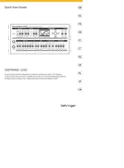
150 RING MOD/NOISE/
S&H/LFO
Legendary Analog Ring Modulator/
Noise/S&H/LFO Module for Eurorack
V 1.0