6LE007919B
Operating and
assembly instructions
2980 xx, 2984 xx, 3080 xx, 3084 xx
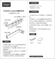
Radio Touch
z
Berker GmbH & Co. KG, Zum Gunterstal, 66440 BLIESKASTEL, GERMANY
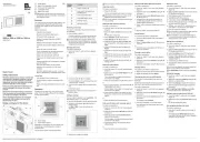
(1) Frame 2gang
(2) Radio Touch application module
(3) Centre plate for loudspeaker
(4) Loudspeaker insert
(5) Radio Touch insert
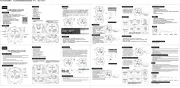
Depending on variant, the scope of delivery for
the radio set includes loudspeaker, design parts
and fastening screws.
Function
The radio receives FM and DAB radio stations, can
be streamed with Bluetooth audio devices and
emits the audio signals via the connected loud-
speakers.
Additional functions:
- Capacitive touch display
- Manual and automatic station search
- 8 FM and 8 DAB storage slots
- Display of reception frequency and RDS
information
- Display of time and date in Standby mode
- Automatic date and time setting on RDS recep-
tion
- Alarm with radio or acoustic signal
- Timer (countdown) with acoustic signal when
expired (also during radio reception)
- Sleep mode with automatic switch-off
- Hotel mode with limited functions can be acti-
vated
- Display brightness can be adjusted in 10 stages
and with 8 times,
black and white display can be inverted
- Extension unit connection, e.g. for switch,
controller
- AUX-IN for external audio sources, e.g. smart-
phone or MP3 player to multimedia socket outlet
Correct use
- Only suitable for use in indoor areas
- Flush-mounting in wall box according to DIN
49073
- Radio and loudspeaker each mounted in a wall
box
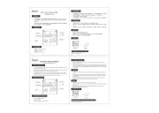
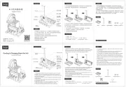
Operation
Operation of the radio solely using touch control
panel. The touch surface (Figure 2) has a display
and six symbol buttons.
Touch
(7)
(6)
22
(6) Touch display
(7) Touch symbol buttons
Depending on the display, the touch display is di-
vided into up to 9 control panels or shows a
multi-line menu.
The six symbol buttons have fixed functions:
Symbol
button
Function
Switch on/switch o
jump back to the higher-level
operating level
scroll up/Increase value
scroll down/reduce value
increase volume
decrease volume
Switching on the radio
The radio is in Standby mode, the time and date
are displayed.
Touch display or button
.
The radio repeats the most recently selected sta-
tion or switches the last function used on again.
In FM and DAB radio operation, details such
as station type, name and frequency, song title,
storage slot and type of playback are displayed,
or alternatively the function.
Selecting menu item
The radio is switched on.
Touch the button
until main menu appears
(Figure 3).
33
Radio FM
Radio DAB+
Bluetooth
AUX In
Setup
Touch the button
/
or the display.
The active display in the central operating panel
- shown in bold - changes.
Touch the active display with the desired menu
item.
A new menu opens.
Longer lines of text are shown in a loop after a
second's delay.
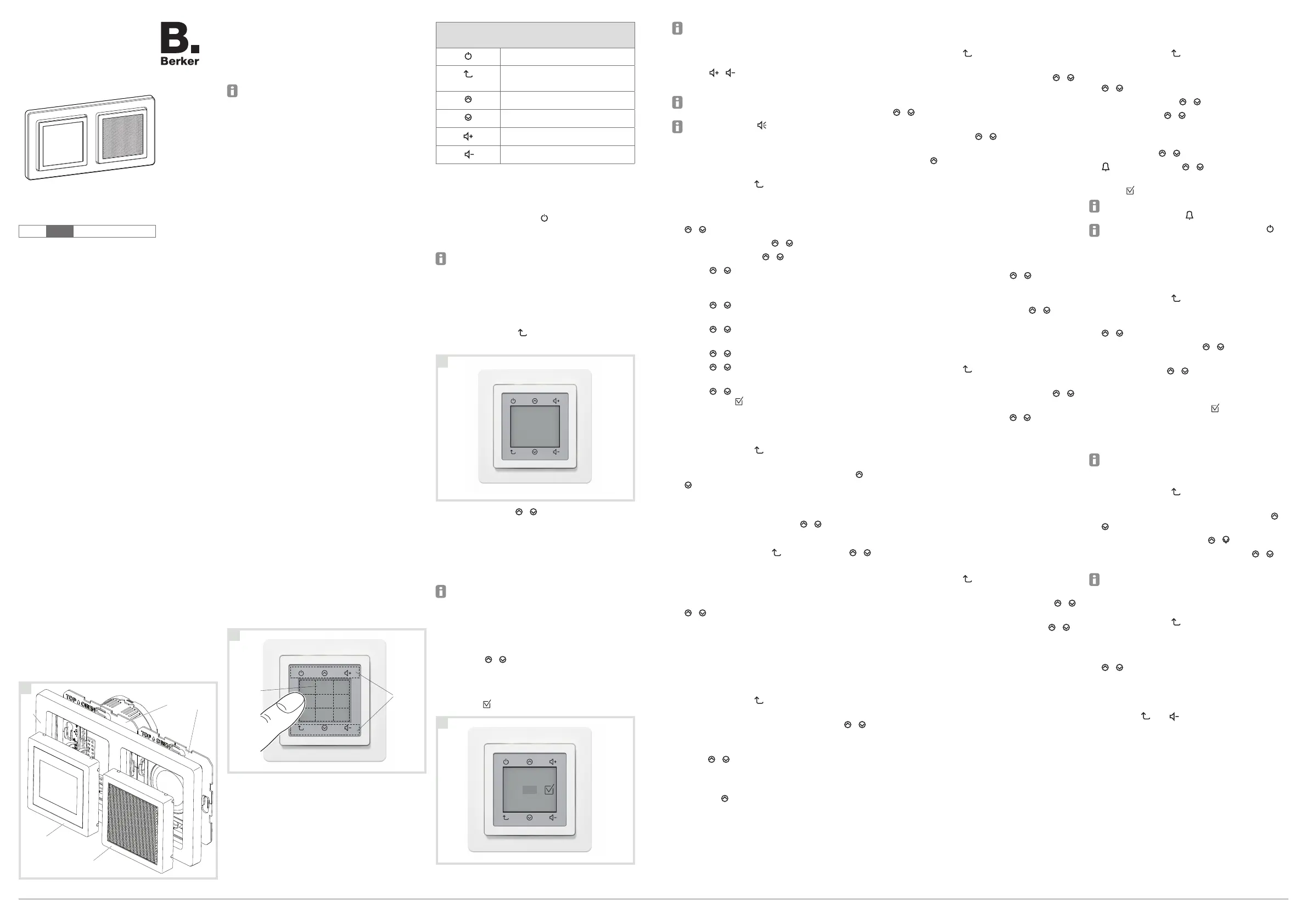
Configure settings
The menu item is selected - e.g. Countdown. The
first setting is active - e.g. Hours Hr.
Use the /
/
button to set the desired number.
Using the control panel, apply the number of
another setting,
e.g. Min or Sec, or save the settings with
(figure 4)
.
44
Adjust other settings accordingly.
The active setting is displayed in square brackets.
Adjusting volume
The radio is switched on.
Press
/
button.
The sound is played back louder/more quietly.
Alternatively, simply swipe up or down on the
displayed volume bar during setting.
With control panel , switched to mute during
volume setting.
Setting the date and time manually
The radio is switched on.
Touch the button
until main menu appears
(Figure 3).
Select the Alarm and time control panel with
the
/ buttons
and press it.
Select Date/time with
/
and press it.
Select Manual with
/
and
press it.
Using
/ , select the date format EU / US
and, using another control panel, apply, e.g.
Year.
Using
/ , select the year and apply with
Month.
Using
/ , select the month and apply with
Day.
Using
/ , select the day and apply with Hr.
Using
/ , select the hour and apply with
Min.
Using
/ , select the minutes and apply all
settings with .
Setting the DAB stations
The radio is switched on.
Touch the button
until main menu appears
(Figure 3).
Select the control panel DAB+ Radio using
/
and press it.
The most recently set station is played back
and shown in the display.
Select the saved station using
/
and press it.
or:
Go up one level using
and select using
/
“New station” and
press it.
The first station in the station list is played back
and shown in the display.
Select another station in the station list using
/
einen anderen Sender der Stationsliste
wählen.
or:
Save the station (see Saving stations).
Setting an FM station with automatic search
The radio is switched on.
Touch the button
until main menu appears
(Figure 3).
Select the control panel FM Radio using
/
and press it.
Select the control panel Automatic Search
using
/
and press it.
The first station to be found will be played back
and shown in the display.
Pressing
continues the automatic search
without saving.
or:
Save the station (see Saving stations).
Setting an FM station with manual search
The radio is switched on.
Touch the button
until main menu appears
(Figure 3).
Select the control panel FM Radio using
/
and press it.
Select the control panel Manual Search using
/
and press it.
Increase/reduce the reception frequency in
0.1 MHz steps using
/
until a station is
received without interference.
Press to
continue the manual search without
saving.
or:
Save the station (see Saving stations).
Saving stations
The searched for station is played back.
Press the station display in the control panel.
Press Save.
Select theNew station using
/
and press
it to save.
or:
Select the saved radio station with
/
and
press it to overwrite.
Opening a saved station
The radio is switched on.
Touch the button
until main menu appears
(Figure 3).
Select the control panel FM Radio using
/
and press it.
Select the saved station using
/
and press it.
Deleting stations
The station to be deleted is played back.
Press the control panel with the station display.
Delete this storage slot using Delete.
Connecting audio devices with Bluetooth
This function is only available in the radio with
Bluetooth.
A maximum of 8 Bluetooth devices can be stored.
Only one of them can be connected at a time.
The radio is switched on.
Touch the button
until main menu appears
(Figure 3).
Select the control panel Bluetooth using
/
and press it.
Select the control panel Connect using
/
and press it.
The display shows Connect.
Connect to Bluetooth on the audio device.
The radio plays the audio signals sent by the
audio device.
Setting the alarm
The radio is switched on.
Touch the button
until main menu appears
(Figure 3).
Select the Alarm and time control panel with the
/ buttons
and press it.
Select Alarm using
/ and
press it.
SelectOn using
/ and
press it.
If necessary, switch to 24h/AM/PM display.
Press the time to be set
(hours or minutes).
Set
the time using
/
(Figure 2).
Press and, using
/ , select and press a
radio station or the electronic alarm signal
.
Press
to apply the settings.
When the alarm is active and the radio switched
off, the alarm symbol is displayed.
Alarm operations can be terminated using
or moved by intervals of 5 minutes (snooze) by
pressing another control panel.
Setting timer (countdown)
The radio is switched on.
Touch the button
until main menu appears
(Figure 3).
Select the Alarm and time control panel with the
/ buttons
and press it.
Select Countdown suing
/ and
press it.
Press the time to be set
(hours, minutes or
seconds).
Using
/ , set the time shown in
brackets
(Figure 4).
If necessary, set additional times.
Apply the time setting using
and activate the
countdown.
After the time has elapsed, an acoustic signal will
sound - even if radio is being received.
The Sleep Mode function can be set accordingly.
Setting the language
Touch the button
until main menu appears
(Figure 3).
Select the control panel Settings using the
/
buttons
and press them.
Select theLanguage using
/
and press it.
Select the appropriate language using
/
and
press it.
The Lighting, Default Settings and Audio
functions can be set in the same way.
Setting to external audio device (AUX IN)
Touch the button
until main menu appears
(Figure 3).
Select the control panel External Input musing
the
/ buttons
and press them.
Activating/deactivating hotel mode
The radio is switched on.
Press the
and buttons for more than 10
seconds
The display shows Hotel mode on and the
menu items FM Radio, DAB+ Radio, Bluetooth
and Alarm can be selected.
z
Radio Touch
Safety instructions
Electrical equipment must only be installed and
assembled by a qualified electrician in accord-
ance with the relevant installation standards,
regulations, directives and safety and accident
prevention directives of the country.
Failure to comply with these instructions may
result in damage to the device, fire or other
hazards.
Disconnect load before working on the device.
Take into account all circuit breakers that sup-
ply dangerous voltages to the device.
These operating instructions are an integral
component of the product, and must be re-
tained by the end user.
Design and layout of the device
11
(1)
(2)
(3)
(4)
(5)