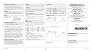
Block AIM 1,6/0,8 Manual


Læs nedenfor 📖 manual på dansk for Block AIM 1,6/0,8 (2 sider) i kategorien Ikke kategoriseret. Denne guide var nyttig for 4 personer og blev bedømt med 4.7 stjerner i gennemsnit af 2.5 brugere

Side 1/2
Data SheetDisposal
Please observe the current regulations and dispose according to type of material
i. e. as electronic scrap (printed circuit boards), plastics (housing), steel, copper etc.
Amendments
We have produced this documentation with the utmost care, however no guarantee
for completeness or correctness can be given. The adoption of this information in
an application must be individually checked. The technical details describe the
product features without guaranteeing these. This product is subject to changes
Operation Information
The natural cooling of this equipment must not be impaired. An unobstructed air
circulation and a distance of at least 30 mm to neighbouring components should
be observed.
The transformer must be disconnected from the mains supply before replacing
blown fuses, or wiring of the terminals.
Due to the protection index (IP 20), the use of this equipment is only permitted in
dry areas.
This transformer does not provide isolation from mains voltage.
Connection plan
The input, output connection terminals and output fuse link are in the same com-
partment at one end of the housing. In the compartment at the other end are the
terminals and jumpers which enable the required (input and output voltages to be
chosen).
(AIM 10/5; AIM 16/8 on one terminal block).
Required Jumper Required Jumper
input voltage between output voltage between
240 V B - 1 240 V A - 1
230 V B - 2 230 V A - 2
220 V B - 3 220 V A - 3
115 V B - 4 115 V A - 4
Example for application:
Input voltage 220 V, output voltage 240 V
jumper between B - 3 and A - 1
Dependant on the input voltage setting, the max. current that can be drawn from
the output is limited to the values that can be taken from the data sheet.
The standard voltage settings on delivery are 240 V input and 115 V output.
A secundary fuse link for the smaller current rating at 115 V input voltage, is
secured in the cover of the terminal compartment.
To secure the voltage isolation values of the load, the common auto - transformer
point ”N and N’” should be connected to the mains neutral lead.
V
!
Safety and user Information
Congratulations to the ownership of this high quality product. A long life expectancy
is assured if used in the described manner and correct application. As with all
technical products, a hazard to health or equipment can exist if improperly used,
the unauthorized removal of necessary covers, incorrect installation or incorrect
operation is present. Follow these instructions and adhere to the generally accepted
rules of technology. Installation and setting-up should only be carried out by qualified
personnel (IEC 60364 / VDE 0105).
Packaging
Carefully check the equipment immediately after receipt, for transport damage,
deformation, and loose parts. Any damage should be reported without delay to the
transport carrier, even then when no apparent damage to external packaging is
visible.
Storage
Permitted storage temperature : -25°C...+85°C
Permitted humidity : 30...80 % relative humidity
No condensation during operation.
Extended storage : Equipment containing capacitors
should be connected to the mains
supply for at least 5 min. every
two years.
Installation and Operation
This equipment is to be protected against improper use. Components are not to be
bent or isolation spacings to be changed, when transported or handled. The contact
with electrical components and terminals is to be avoided.
Always disconnected the equipment from the mains supply before installation or
wiring is started!
During operation this equipment can have (depending on the protection index)
hazardous live parts or hot surfaces. The product desciption, technical information
in our main catalogue and the marking on the equipment and ratings plate are to
be observed. The installation must be carried out according to the prevailing local
conditions, prevailing safety standards (e. g. VDE 0100), national accident preven-
tion regulations (e. g. UVV - VBG 4; BGV A 2 respectively) and the generally
accepted rules of technology.
This equipment can be used independantly or as a component for electrical
installation or machines, and fulfils the requirements of the low voltage guidelines
(73/23/EWG). When installed into machinery, the normal operation is forbidden
until it is determined that the machine fulfils the requirements of the machinery
guidelines (89/392/EWG), attention must be paid to EN 60 204. Normal operation
in the intended use can only begin when the EMC guidelines (89/336/EWG) are
fulfilled. The observance of the required limitations for the EMC legislation, is the
responsibility of the manufacturer of the installation or machinery.
Maintenance and Servicing
Electrical equipment generally requires no special maintenance, are however
(depending on the protection index) to be protected against dust build-up, moisture,
radiation and aggressive chemicals. Servicing is only permitted under the terms
and conditions of these operating instructions. Nevertheless should a failure occur,
please return the equipment to us for repair giving the following information: Type
of fault, accompanying symptoms (operation conditions), your own speculation as
to the cause of the failure, previous unusual conditions etc..
Type Input Output Output no load Specified fuse Weight
voltage voltage current losses value
V V A typ. W AT kg
AIM 1,6/0,8 220 / 230 / 240 115 / 220 / 230 / 240 1,6 4,7 1,6 2,10
115 220 / 230 / 240 0,8 4,7 0,8 2,10
AIM 3,2/1,6 220 / 230 / 240 115 / 220 / 230 / 240 3,2 6,7 3,2 3,60
115 220 / 230 / 240 1,6 6,7 1,6 3,60
AIM 5,0/2,5 220 / 230 / 240 115 / 220 / 230 / 240 5,0 11,8 5,0 5,00
115 220 / 230 / 240 2,5 11,8 2,5 5,00
AIM 10/5 220 / 230 / 240 115 / 220 / 230 / 240 10,0 18,0 10 AgG 12,10
115 220 / 230 / 240 5,0 18,0 5,0 AT0
AIM 16/8 220 / 230 / 240 115 / 220 / 230 / 240 16,0 21,0 16 AgG 16,50
115 220 / 230 / 240 8,0 21,0 8,0 AgG0
Diagramm
(factory setting)
AIM 1,6/0,8; AIM 3,2/1,6; AIM 5,0/2,5
AIM 10/5; AIM 16/8
BLOCK Transformatoren-Elektronik
Gebrauchsanleitung
Spartransformator Typ AIM
Instruction leaflet
Auto transformer Type AIM
BLOCK Transformatoren-Elektronik GmbH
Max-Planck-Straße 36-46 • 27283 Verden • Germany
Phone: +49 4231 678-0 • Fax: +49 4231 678-177
info@block-trafo.de • www.block-trafo.de
BLOCK Belgium BVBA
Nieuwstraat 2 • 3200 Aarschot • Belgium
Phone: +32 16 69 45 • Fax: +32 16 69 79 72
info@block-trafo.com • www.block-trafo.com
BLOCK UK LTD.
24 Bentalls Centre, Colchester Road
Heybridge • Maldon, Essex CM9 4GD • United Kingdom
Phone: +44 1621 85-06 66 • Fax: +44 1621 85-07 11
info@block-trafo.com • www.block-trafo.com
BLOCK USA Inc.
1370 Bowes Road, Suite 110
Elgin • Illinois 60123
Phone: +1 847 214 8900 • Fax: +1 224 569 4312
www.blockusa.com • info@blockusa.com
Stand: 04/2011
Unbenannt-2.indd 1 05.04.11 11:41
Im Auslieferungszustand ist der Transformator auf 240 V Eingangsspannung und
115 V Ausgangsspannung eingestellt. Eine zweite Sicherung für den kleineren
Nennstrom (bei 115 V Eingangsspannung) ist in der Abdeckung untergebracht.
Um die Isolationswerte der Verbraucher nicht zu übersteigen, ist N und N’ an den
Neutralleiter zu schalten.
Datenblatt
Typ Eingangs- Ausgangs- Ausgangs- Leerlauf- vorgeschriebener Gewicht
spannung spannung strom verluste Sicherungswert
V V A typ. W AT kg
AIM 1,6/0,8 220 / 230 / 240 115 / 220 / 230 / 240 1,6 4,7 1,6 2,10
115 220 / 230 / 240 0,8 4,7 0,8 2,10
AIM 3,2/1,6 220 / 230 / 240 115 / 220 / 230 / 240 3,2 6,7 3,2 3,60
115 220 / 230 / 240 1,6 6,7 1,6 3,60
AIM 5,0/2,5 220 / 230 / 240 115 / 220 / 230 / 240 5,0 11,8 5,0 5,00
115 220 / 230 / 240 2,5 11,8 2,5 5,00
AIM 10/5 220 / 230 / 240 115 / 220 / 230 / 240 10,0 18,0 10 AgG 12,10
115 220 / 230 / 240 5,0 18,0 5,0 AT0
AIM 16/8 220 / 230 / 240 115 / 220 / 230 / 240 16,0 21,0 16 AgG 16,50
115 220 / 230 / 240 8,0 21,0 8,0 AgG0
Wartung und Instandhaltung
Elektrische Betriebsmittel bedürfen in der Regel keiner besonderen Wartung, sind
jedoch (der Schutzart entsprechend) vor Staubablagerung, Feuchte, Strahlung und
aggressiven Chemikalien zu schützen. Die Instandsetzung ist nur im Rahmen
dieser Gebrauchsanleitung aufgeführten Maßnahmen statthaft. Sollte es dennoch
einen Ausfall geben, schicken Sie bitte das Betriebsmittel zur Reparatur an uns
ein. Geben Sie bitte folgendes an: Art des Fehlers, Begleitumstände (Einsatzbedin-
gungen), eigene Vermutungen über die Fehlerursache, vorausgegangene ungewöhn-
liche Vorkommnisse etc..
Entsorgung
Bitte beachten Sie die aktuellen Bestimmungen und entsorgen Sie je nach Be-
schaffenheit z. B. als Elektronikschrott (Leiterplatten), Kunststoff (Gehäuse), Blech,
Kupfer, usw..
Änderungen
Unser Haus hat die Produktdokumentation mit großer Sorgfalt erstellt und ge-
prüft. Es kann jedoch keine Gewährleistung bezüglich der Fehlerfreiheit und Voll-
ständigkeit übernommen werden. Eine Übertragbarkeit der Angaben auf die je-
weilige Anwendung ist zu prüfen. Die technischen Daten beschreiben die Eigen-
schaften des Produktes, ohne diese zuzusichern. Änderungen, die dem technischen
Fortschritt dienen, sind vorbehalten.
Betriebshinweise
Die Kühlung des Betriebsmittels darf nicht beeinträchtigt werden. Eine ungehinder-
te Luftzufuhr und ein Mindestabstand von 30 mm zu benachbarten Teilen ist
sicherzustellen.
Wechseln Sie defekte Sicherungen nur im spannungslosen Zustand aus.
Die Verdrahtung der Anschlussklemmen darf nur im spannungslosen Zustand
erfolgen.
Aufgrund der Schutzart (IP20) ist der Betrieb des Gerätes nur in trockenen
Räumen zulässig.
Der Transformator besitzt keine galvanische Trenung vom Netz.
Anschlussplan
Die Anschlussklemmen Eingang und Ausgang sowie die Ausgangssicherung befin-
det sich auf einer Seite des Gehäuses.
Auf der gegenüberliegenden Seite wird durch Umklemmen die Ein- und
Ausgangsspannung bestimmt.
(AIM 10/5; AIM 16/8 in einer Klemmenreihe).
Eingangs- Brücke Ausgangs- Brücke
spannung zwischen spannung zwischen
240 V B - 1 240 V A - 1
230 V B - 2 230 V A - 2
220 V B - 3 220 V A - 3
115 V B - 4 115 V A - 4
Anwendungsbeispiel;
Eingang 220 V, Ausgang 240 V
Brücke zwischen B - 3 und A - 1
Bei den jeweiligen Eingangsspannungen ergeben sich entsprechende zulässige
Ausgangsströme. Die Werte entnehmen Sie dem Datenblatt.
V
!
Abmessungen Sicherheits- und Anwendungshinweise
Wir beglückwünschen Sie zum Erwerb dieses hochwertigen Produkts. In dem
beschriebenen Anwendungsbereich wird es im bestimmungsgemäßen Betrieb
lange seine Funktion erfüllen. Wie bei jedem technischen Produkt kann jedoch die
Gefahr von schweren Personen- oder Sachschäden bei unsachgemäßem Einsatz,
unzulässigem Entfernen von erforderlichen Abdeckungen, bei falscher Installation
oder Bedienung bestehen. Folgen Sie dieser Gebrauchsanleitung und verfahren Sie
nach den anerkannten Regeln der Technik. Alle Arbeiten zur Installation, Inbetrieb-
nahme und Betrieb sowie zur Instandhaltung sind von qualifiziertem Fachpersonal
auszuführen. (IEC 60364 / VDE 0105)
Verpackung
Bitte untersuchen Sie das Betriebsmittel sofort auf Transportschäden wie Defor-
mation und lose Teile. Beschädigungen bitte unverzüglich beim Transportunterneh-
men reklamieren; auch dann, wenn die Verpackung äußerlich nicht beschädigt ist.
Lagerung
zulässige Lagerungstemperatur : -25°C...+85°C
zulässige Luftfeuchtigkeit : 30...80 % relative Feuchte; bei
Inbetriebnahme darf keine
Betauung vorliegen
bei Langzeitlagerung : Betriebsmittel mit eingebautem
Kondensator sind mindestens alle
2 Jahre für 5 min. an Netzspannung
anzulegen.
Installation und Inbetriebnahme
Das Betriebsmittel ist vor unzulässiger Beanspruchung zu schützen. Insbesondere
dürfen bei Transport und Handhabung keine Bauelemente verbogen und/oder
Isolationsabstände verändert werden. Die Berührung elektronischer Bauelemente
und Kontakte ist zu vermeiden.
Den geforderten Mindestabstand zu benachbarten Teilen unbedingt einhalten um
die Kühlung nicht zu behindern! Während des Betriebes kann das Betriebsmittel
(der Schutzart entsprechend) spannungsführende, blanke sowie heiße Oberflächen
besitzen. Betriebsmittel immer im spannungsfreien Zustand montieren und ver-
drahten.
Die Produktbeschreibung und die technischen Hinweise in unserem Hauptkatalog,
sowie die Aufschriften am Betriebsmittel und auf dem Typenschild sind zu beach-
ten.
Die Installation ist entsprechend den örtlichen Gegebenheiten, einschlägigen Vor-
schriften (z. B. VDE 0100), nationalen Unfallverhütungsvorschriften (z. B. UVV-VBG
4 bzw. BGV A 2) und den anerkannnten Regeln der Technik durchzuführen.
Dieses elektrische Betriebsmittel kann eigenständig oder als Komponente, die zum
Einbau in elektrische Anlagen oder Maschinen bestimmt ist, betrieben werden. Es
erfüllt die Anforderungen der Niederspannungsrichtlinie (73/23/EWG). Bei Einbau
in Maschinen ist die Aufnahme des bestimmungsgemäßen Betriebes solange
untersagt, bis festgestellt wurde, dass die Maschine den Bestimmungen der
Maschinenrichtlinie (89/392/EWG) entspricht; EN 60 204 ist zu beachten. Die
Aufnahme des bestimmungsgemäßen Betriebes ist nur bei Einhaltung der EMV-
Richtlinie (89/336/EWG) erlaubt. Die Einhaltung der durch die EMV-Gesetzgebung
geforderten Grenzwerte liegt in der Verantwortung des Herstellers der Anlage
oder Maschine.
Aufbauskizze
(Auslieferungszustand)
AIM 1,6/0,8
AIM 3,2/1,6
AIM 5,0/2,5
AIM 10/5; AIM 16/8
AIM 1,6/0,8; AIM 3,2/1,6; AIM 5,0/2,5
AIM 10/5; AIM 16/8
Unbenannt-2.indd 2 05.04.11 11:41


Produkt Specifikationer

Mærke: Block
Kategori: Ikke kategoriseret
Model: AIM 1,6/0,8

Har du brug for hjælp?

Hvis du har brug for hjælp til Block AIM 1,6/0,8 stil et spørgsmål nedenfor, og andre brugere vil svare dig