Montage- und Betriebsanleitung
Installation and Operating Instructions
Mode d´emploi
Montage- en bedieningshandleiding
Istruzioni per l´uso
Instrucciones de montaje de servicio
Bruksanvisning för montering och drift
6186 USB
USB-Schnittstelle
USB Interface
Interface USB
USB-Interface
Interfaccia USB
Interfaz USB
USB-gränssnitt
Busch-Installationsbus® KNX
GJB0007082P0002
0173-1-6534/15.04.2016
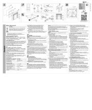
Technische Daten (Auszug)
EIB Betriebs-
spannung Versorgung über EIB
USB Betriebs-
spannung Versorgung über USB
Anschlüsse
KNX über Busanschlussklemme
USB über USB Buchse
Verlustleistung P max. 0,54 W
Temperaturbereich 0 °C ... + 45 °C (Betrieb)
-25 °C ... + 55 °C (Lagerung)
Schutzart IP20, nach DIN EN 60 529
Schutzklasse III
Überspannungs-
kategorie III nach EN 60 664-1
Verschmutzungsgrad
2 nach EN 60 664-1
Luftdruck Atmosphäre bis 2.000 m
Montage auf Tragschiene 35mm,
DIN EN 60 715
Abmessungen 90 x 36 x 64 mm (H x B x T)
Breite in TE 2, 2 Module á 18 mm
Gerätetyp Reiheneinbaugerät, REG
Geräte-Anschluss
1 Schilderträger
2 Programmier-Taste
3 Programmier-LED
4 Busanschlussklemme
5 EIB-LED
6 USB-LED
7 USB Buchse
Geräte-Beschreibung
Die USB-Schnittstelle 6186 USB ermöglicht die
Kommunikation zwischen der ETS und der zu
programmierenden EIB Anlage. Durch die EIB-
LED und die USB-LED wird die Kommunikation
zwischen den beiden Bussystemen dargestellt.
Die USB-Schnittstelle funktioniert ab der
Engineering Tool Software ETS 3.
DE Montage
Das Gerät ist geeignet zum Einbau in Verteilern oder
Kleingehäusen für Schnellbefestigung auf 35 mm
Tragschienen, nach DIN EN 60 715.
Die Zugänglichkeit des Gerätes zum Betreiben,
Prüfen, Besichtigen, Warten und Reparieren muss
sichergestellt sein.
Anschluss
Die Verbindung zum KNX erfolgt mit der
mitgelieferten Busanschlussklemme. Über
die USB Buchse wird der USB Teilnehmer
angeschlossen.
Inbetriebnahme
Das Gerät zuerst an den KNX und anschließend
an den USB anschließen. Die USB-Schnittstelle
funktioniert ab der Engineering Tool Software
ETS 3.
Eine ausführliche Beschreibung der Para-
metrierung und Inbetriebnahme finden Sie in den
technischen Daten des Gerätes.
Diese finden Sie zum Download im Internet unter
www.BUSCH-JAEGER.de.
Wichtige Hinweise
Warnung! Installation nur durch elektrotechnische
Fachkraft. Bei der Planung und Errichtung von
elektrischen Anlagen sind die einschlägigen
Norme n, Richt l i nien, Vo r s c hriften und
Bestimmungen zu beachten.
- Gerät bei Transport, Lagerung und im Betrieb
vor Feuchtigkeit, Schmutz und Beschädigung
schützen!
- Gerät nur innerhalb der spezifizierten
technischen Daten betreiben!
- Gerät nur im geschlossenen Gehäuse
(Verteiler) betreiben!
Reinigen
Verschmutzte Geräte können mit einem trockenen
Tuch gereinigt werden. Reicht dies nicht aus, kann
ein mit Seifenlösung leicht angefeuchtetes Tuch
benutzt werden. Auf keinen Fall dürfen ätzende
Mittel oder Lösungsmittel verwendet werden.
Wartung
Das Gerät ist wartungsfrei. Bei Schäden (z.B. durch
Transport, Lagerung) dürfen keine Reparaturen
vorgenommen werden.
Beim Öffnen des Gerätes erlischt der Garantie-
anspruch!
1
1
Installation
The device is suitable for installation in distribution
boxes or small housings for quick mounting on
35 mm support rails in compliance with DIN
EN 60715. The accessibility of the device for
operation, testing, inspection, maintenance and
repair must be ensured.
Connection
The connection to the KNX is made using the bus
connection terminal supplied. The USB device is
connected through the USB socket.
Commissioning
The device is connected first to the KNX and then
to the USB. Die USB interface functions with the
ETS 3 Engineering Tool Software or higher.
A detailed description of the parameter
configuration and commissioning steps can be
found in the technical data. This information can
be downloaded from the Internet site
www.BUSCH-JAEGER.de.
Important notes
Warning! Installation by person with electrotechnical
expertise only. The relevant standards, directives,
regulations and instructions must be observed
when planning and implementing the electrical
installation.
- Protect the device against moisture, dirt and
damage during transport, storage and
operation!
- Do not operate the device outside the specified
technical data (e.g. Temperature range)!
- The device may only be operated in closed
enclosures (e.g. distribution boards)
Cleaning
Should the device become soiled, it may be
cleaned with a dry cloth. If this does not suffice,
a cloth lightly moistened with soap solution may
be used. On no account should caustic agents or
solvents be used.
Maintenance
The device is maintenance free. Should damage
have occurred, e.g. due to transport or storage,
no repairs should be carried out.
The warranty expires if the device is opened!
Vous trouverez une description détaillée du
paramétrage et de la mise en service dans la
documentation technique de l’appareil. Vous
pouvez télécharger celles ci par Internet, sur le
site www.BUSCH-JAEGER.de.
Remarques importantes
Avertissement! Installation uniquement par des
personnes qualifiées en électrotechnique. Les
normes, directives, règlements et stipulations
en vigueur doivent être respectés lors de la
planification et de la mise en place d’installations
électriques.
- Protéger l’appareil de l’humidité, de la saleté
et de dommage lors du transport, du stockage
et de l’utilisation !
- N’utiliser l’appareil que dans le cadre des
caractéristiques techniques spécifiées !
- N’utiliser l’appareil que dans un boîtier fermé
(coffret) !
Nettoyage
Les appareils sales peuvent être nettoyés à l’aide
d’un chiffon sec. Si cela ne suffit pas, un chiffon
légèrement imprégné de solution savonneuse
peut être utilisé. N’utiliser en aucun cas des
produits caustiques ou des solvants.
Entretien
L’appareil ne nécessite aucun entretien. En cas de
dommage (par ex. lors du transport, du stockage),
aucune réparation ne doit être entreprise.
L’ouverture de l’appareil annule la garantie !
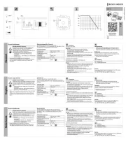
Bedienung und Anzeige
Programmier-Taste (2)
zur Vergabe der physikalischen
Adresse, siehe Programmier-LED (3)
Programmier-LED in rot (3)
Ist an, nachdem die Programmier-
taste (2) gedrückt wurde, um dem
Busteilnehmer eine physikalische
Adresse zu vergeben.
EIB-LED in gelb (5)
Ist an, sobald der EIB Teilnehmer
angeschlossen und betriebsbereit ist.
Blinkt, sobald Telegrammverkehr auf
dem EIB stattfindet.
USB-LED in gelb (6)
Ist an, sobald der KNX und der
USB Teilnehmer angeschlossen und
betriebsbereit sind.
Blinkt, sobald Telegrammverkehr
zwischen USB und EIB stattfindet.
Technical Data (extract)
EIB operating
voltage Supply through EIB
USB operating
voltage Supply through USB
Connections
KNX Through bus connection
terminal
USB Through USB socket
Power loss P max. 0.54 W
Temperature range 0°C ... + 45°C (operation)
-25°C ... + 55°C (storage)
Type of protection IP20, in compliance with
DIN EN 60 529
Protection class III
Overvoltage category
III according to EN 60 664-1
Pollution degree 2 according to EN 60 664-1
Atmospheric pressure
Atmosphere up to 2,000 m
Installation On 35 mm support rails,
DIN EN 60 715
Dimensions 90 x 36 x 64 mm (H x W x D)
Width in TE 2, 2 Modules of 18 mm
Type of device Installed in rows, REG
Device Connection
1 Nameplate support
2 Programming key
3 Programming LED
4 Bus connection terminal
5 EIB LED
6 USB LED
7 USB socket
Description of the Device
The 6186 USB interface enables communications
between the ETS and the EIB system to be
programmed. The communication between the
two bus systems is represented by the EIBLED
and the USB-LED. The USB interface functions
with the ETS 3 Engineering Tool Software or
higher.
EN
1Operation and Display
Programming key (2)
To assign the physical address, see
programming LED (3).
Programming LED in red (3)
Is on after the programming key (2)
has been pressed, to assign a physical
address to the bus device.
EIB LED in yellow (5)
Is on as soon as the EIB device is
connected and ready for operation.
Blinks as soon as telegram traffic takes
place on the EIB.
USB LED in yellow (6)
Is on as soon as the KNX and the USB
devices are connected and ready for
operation.
Blinks as soon as telegram traffic takes
place between the USB and the EIB.
Montage
L’appareil se prête à un montage dans des
tableaux de distribution ou dans de petits boîtiers
destinés à une fixation rapide sur des profilés
support de 35 mm, selon DIN EN 60 715. Il est
indispensable que l’accessibilité de l’appareil
soit assurée pour les tâches d’exploitation, de
vérification, de visite, d’entretien, de maintenance
et de réparation.
Connexion
La liaison au KNX s’opère par la borne de
raccordement de bus fournie. C’est via le
connecteur femelle USB que la station USB est
raccordée.
Mise en service
Raccordez l’appareil tout d’abord au KNX puis
au USB. L’interface USB fonctionne à partir du
logiciel Engineering Tool Software ETS 3.
Caractéristiques techniques (extrait)
Tension de service
EIB Alimentation via EIB
Tension de service
USB Alimentation via USB
Connexions
KNX via borne de raccordement
de bus
USB via connecteur femelle USB
Puissance dissipée P
max. 0,54 W
Gamme de t
empérature 0° C ... + 45° C (exploitation)
-25° C ... + 55° C (stockage)
Protection IP20, selon DIN EN 60 529
Classe de protection III
Classe de surtension
III selon EN 60 664-1
Degré de contamination
2 selon EN 60 664-1
Pression atmosphérique
Atmosphère jusqu‘à 2 000 m
Montage sur profilé support 35 mm,
DIN EN 60 715
Dimensions 90 x 36 x 64 mm (H x L x P)
Largeur en unités
de profondeur (= TE) 2, 2 modules de 18 mm
Type d’appareil Appareil pour montage
série, REG
Raccordement d’appareil
1 Porte-plaque signalétique
2 Touche de programmation
3 DEL de programmation
4 Borne de raccordement de bus
5 DEL EIB
6 DEL USB
7 Connecteur femelle USB
Description de l’appareil
L’interface 6186 USB assure la communication
entre l’unité ETS et l’installation EIB à programmer.
La DEL EIB et la DEL USB représentent la
communication entre les deux systèmes de bus.
L’interface USB requiert le logiciel Engineering
Tool Software ETS 3 ou plus récent.
FR
1Commande et affichage
Touche de programmation (2)
pour l’assignation de l’adresse physique,
cf. DEL de programmation (3)
DEL de programmation, rouge (3)
Est allumée après avoir appuyé
sur la touche de programmation (2)
pour assigner une adresse physique à
l’abonné bus.
DEL EIB, jaune (5)
Est allumée dès que la station EIB est
raccordée et prête à fonctionner.
Clignote dès que la communication
sur l’EIB a lieu.
DEL USB, jaune (6)
Est allumée dès que l’KNX et la
station USB sont raccordés et prêts
à fonctionner.
Clignote
dès que la communication entre l’USB
et l’EIB a lieu
DE
EN
FR
NL
IT
ES
SE
IP20
0 °C
+45 °C
Busch-Jaeger Elektro GmbH
Ein Unternehmen der ABB-Gruppe
Freisenbergstraße 2
D-58513 Lüdenscheid
Zentraler Vertriebsservice
Tel: +49 2351 956-1600
www.BUSCH-JAEGER.de