Canarm BI-20RM Manual
Læs gratis den danske manual til Canarm BI-20RM (4 sider) i kategorien Emhætte. Denne vejledning er vurderet som hjælpsom af 24 personer og har en gennemsnitlig bedømmelse på 4.9 stjerner ud af 12.5 anmeldelser.
Har du et spørgsmål om Canarm BI-20RM, eller vil du spørge andre brugere om produktet?
Produkt Specifikationer
| Mærke: | Canarm |
| Kategori: | Emhætte |
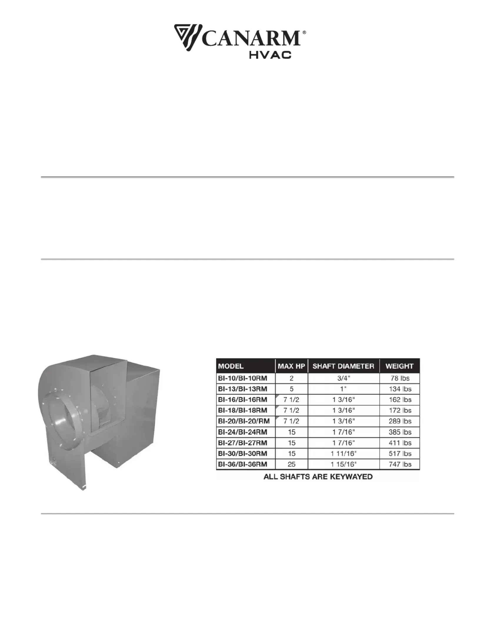
| Model: | BI-20RM |
Har du brug for hjælp?
Hvis du har brug for hjælp til Canarm BI-20RM stil et spørgsmål nedenfor, og andre brugere vil svare dig
Emhætte Canarm Manualer


Emhætte Manualer
- Rommer
- Corbero
- Ersa
- Fulgor Milano
- Marynen
- Tecnolux
- Mepamsa
- Gurari
- Grundig
- Junker
- Kernau
- Frilec
- Lamona
- Boretti
- Hansa
Nyeste Emhætte Manualer


