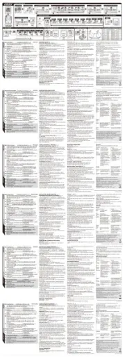
Cannondale IQ400 Manual
Cannondale
Cykel computer
IQ400

| Mærke: | Cannondale |
| Kategori: | Cykel computer |
| Model: | IQ400 |
Har du brug for hjælp?
Hvis du har brug for hjælp til Cannondale IQ400 stil et spørgsmål nedenfor, og andre brugere vil svare dig
Cykel computer Cannondale Manualer

18 August 2024

16 August 2024

14 August 2024

14 August 2024

14 August 2024
Cykel computer Manualer
- Contec
- Echowell
- Halfords
- Sigma Sport
- BTwin
- Sunding
- Asaklitt
- Stella
- Polar
- Ascent
- Assize
- Pro
- Ciclo
- Prophete
- Timex
Nyeste Cykel computer Manualer

30 December 2025
12 Oktober 2024

3 Oktober 2024

2 Oktober 2024
2 Oktober 2024

30 September 2024

29 September 2024
23 September 2024

23 September 2024

23 September 2024