Carrier 06N Manual
Carrier
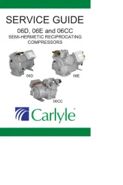
Kompressor
06N
| Mærke: | Carrier |
| Kategori: | Kompressor |
| Model: | 06N |
Har du brug for hjælp?
Hvis du har brug for hjælp til Carrier 06N stil et spørgsmål nedenfor, og andre brugere vil svare dig
Kompressor Carrier Manualer
10 August 2025
9 August 2025

8 Juli 2025
8 Juli 2025
7 Juli 2025
Kompressor Manualer
- DeWalt
- Bavaria
- Herkules
- Kibani
- Vonroc
- NEO Tools
- Anova
- FERM
- Fieldmann
- Duro Pro
- Einhell
- Powerplus
- Topcraft
- Dometic
- Unimac
Nyeste Kompressor Manualer

6 Januar 2026

5 Januar 2026

4 Januar 2026

1 Januar 2026

1 Januar 2026

31 December 2026

31 December 2026

30 December 2026

30 December 2026

30 December 2026