Clarion CJ-981E Manual
Clarion
Ikke kategoriseret
CJ-981E
| Mærke: | Clarion |
| Kategori: | Ikke kategoriseret |
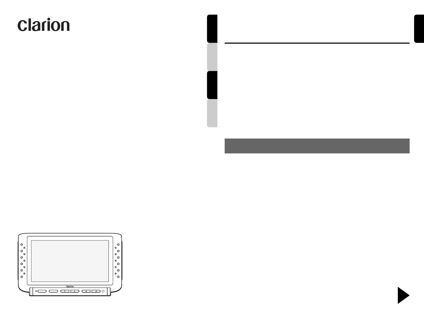
| Model: | CJ-981E |
Har du brug for hjælp?
Hvis du har brug for hjælp til Clarion CJ-981E stil et spørgsmål nedenfor, og andre brugere vil svare dig
Ikke kategoriseret Clarion Manualer
6 Oktober 2025
6 Oktober 2025
5 Oktober 2025
5 Oktober 2025
19 Juli 2025
18 Juli 2025
8 Juni 2025
6 Juni 2025

19 Januar 2025

19 Januar 2025
Ikke kategoriseret Manualer
- Palm
- Silent Angel
- Nord
- EmberGlo
- Sensiplast
- Ibanez
- Whirlpool
- Axxent
- Ignition
- Iiyama
- Atomos
- JBL
- Tiptel
- Airlux
- Mother's Choice
Nyeste Ikke kategoriseret Manualer

1 December 2025

1 December 2025

1 December 2025

1 December 2025

1 December 2025

1 December 2025

1 December 2025

1 December 2025

1 December 2025

1 December 2025