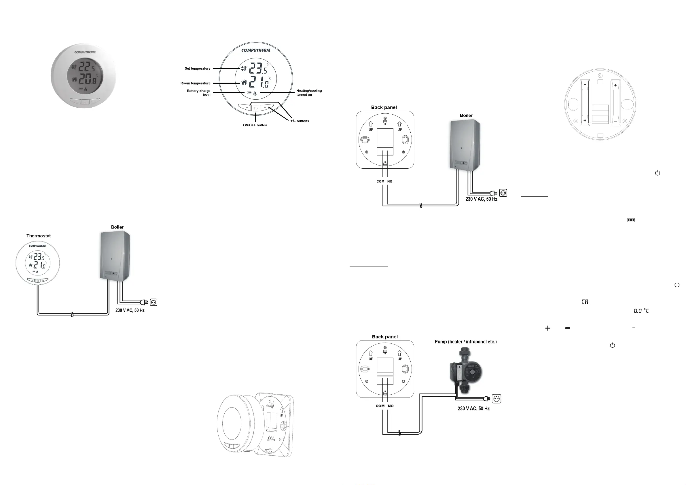
Computherm T30 Manual
| Mærke: | Computherm |
| Kategori: | Ikke kategoriseret |
| Model: | T30 |
Har du brug for hjælp?
Hvis du har brug for hjælp til Computherm T30 stil et spørgsmål nedenfor, og andre brugere vil svare dig
Ikke kategoriseret Computherm Manualer

18 September 2025

18 September 2025

18 September 2025

2 September 2024

2 September 2024

2 September 2024

27 August 2024

25 August 2024

22 August 2024

9 August 2024
Ikke kategoriseret Manualer
- Rocket Espresso
- Roline
- Spirit Of Gamer
- GRAUGEAR
- Grothe
- HMD
- BabyHome
- OKAY
- DVDO
- Auralex
- Glemm
- Suntec
- Toyotomi
- FeiyuTech
- Tech.Inc
Nyeste Ikke kategoriseret Manualer

16 December 2025

16 December 2025

16 December 2025

16 December 2025

16 December 2025

16 December 2025

16 December 2025

16 December 2025

16 December 2025

16 December 2025