direct sunlight, refrigerator, chimney, etc). Do not use in wet,
chemically aggressive or dusty environment. Its optimal location
is 0.75 - 1.5 m above floor level.
IMPORTANT WARNING! If the radiator valves in your at
are equipped with a thermostatic head, adjust it to maximum
temperature or replace the thermostatic head of the radiator
valve with a manual control knob in the room where the room
thermostat is to be located, otherwise the thermostatic head
may disturb the temperature control of the at.
2. INSTALLATION OF THE THERMOSTAT
WARNING! The device must be installed and connected by
a qualied professional! Before installing, make sure that
that neither the thermostat nor the device to be controlled
is connected to the 230 V mains voltage. Modifying the
thermostat can cause electric shock or product failure.
2.1. To install and connect the thermostat you should
perform the following steps:
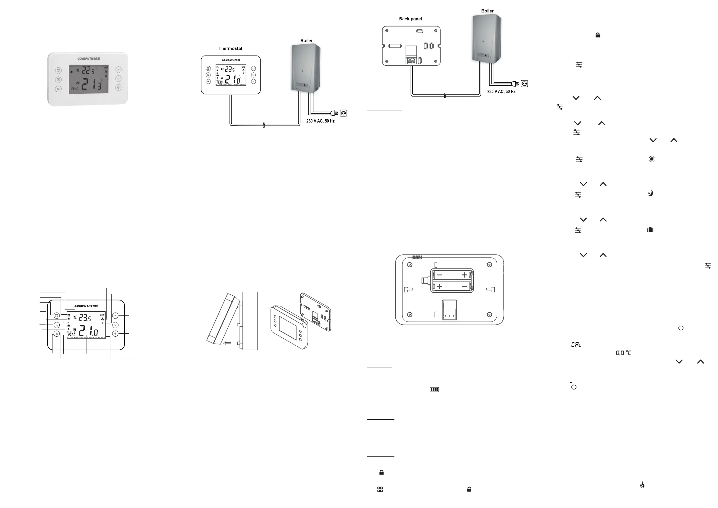
1. Detach the back panel of the thermostat from the front panel
as shown in the gure below.
2. Secure the back panel of the device on the wall using the
supplied mounting screws. Make sure that the arrows on the
back panel are pointing upward.
3. The thermostat controls the boiler or air conditioner through
a potential-free alternating relay that has the following
connection points: NO and COM. These connection points
are on the thermostat wall plate.
4. Connect the two connection points of the heating or cooling
equipment to be controlled to the normally open NO and
COM terminals of the relay.
If you would like to operate an old boiler or any other device
that has no connection points for thermostats, then the NO
and COM connection points of the thermostat should be
connected to the mains cable of the device, similarly as a
switch would be connected.
COMPUTHERM
T70
Programmable wireless (radio-frequency) digital
room thermostat
Instruction Manual
GENERAL DISCRIPTION OF THE
THERMOSTAT
The
COMPUTHERM
T70 type switched-mode room thermostat
is suitable to regulate the overwhelming majority of boilers and
air conditioners available in Hungary. It can be easily connected
to any gas boiler having a two-wire thermostat connection point
and to any air conditioning apparatus or electrical apparatus,
regardless of whether they have a 24 V or 230 V control circuit.
The thermostat can be programmed according to specific needs
so that the heating (cooling) system heats (cools) your home or
office to the desired temperature at the specified times specified,
and it contributes to the reduction of energy costs, in addition to
providing comfort. A daily temperature program can be prepared
for each day of the week, independently of each other. It is
possible to set comfort or economy temperature for each hour of
the day separately.
The simultaneous use of several
COMPUTHERM
room thermostats
and one
COMPUTHERM
Q4Z zone controller provides the
possibility for the thermostats to also control a pump or a zone
valve in addition to starting the heater or cooler. This way it is
easy to divide a heating / cooling system into zones, thanks
to which the heating / cooling of each room can be controlled
separately, thus greatly increasing comfort. Furthermore, the
zoning of the heating / cooling system will greatly contribute to
the reduction of energy costs, as due to this only those rooms
will be heated / cooled at any time where it is required.
1. LOCATION OF THE DEVICE
It is reasonable to locate it in a room used regularly or for many
hours per day so that it is in the direction of natural ventilation
in the room but protected from drought or extreme heat (e.g.
ATTENTION! Always consider the loadability of the thermostat
and follow the manufacturer’s instructions of the heating or
cooling equipment. The device must be installed and connected
by a qualied professional. The voltage appearing at terminals
NO and COM depends only on the system being controlled,
therefore the dimensions of the wires are determined by the type
of the device to be controlled. The length of the wire is of no
signicance.
2.2. Instert the batteries
To put the thermostat into operation you should perform the
following steps:
1. Detach the battery compartment cover.
2. According to the indicated polarities install the two AAA
Micro Alkaline Batteries (LR03 type) provided in the box of
the product into the battery holders.
3. Replace the battery compartment cover and mount the
thermostat onto its wall-mounted supporting bracket.
4.To switch ON the thermostat press once the button located
on the front panel.
Warning! Alkaline batteries may only be used for this appliance.
Carbon-zinc batteries known as durable or long life batteries
and chargeable accumulators are not suitable for the operation
of this appliance. The icon appearing on the display to
indicate low battery voltage warns reliably that the batteries
should be replaced only when alkaline batteries are used.
Attention! After the batteries have been replaced the exact
time and day should be readjusted as described in Chapter
2.4. but the apparatus will memorize the other settings.
2.3. Operation of the key lock
Attention! The thermostat has an automatic key lock function
to prevent accidental modications of settings!
The icon located on the right side of the display indicates
that the key lock is turned on. To turn o the key lock, touch
the
button for 3 seconds and the icon disappears. Now
you can freely use the touch keys of the thermostat until the
automatic key lock is activated again. The key lock turns on 10
seconds after the last key has been touched, indicated by the
appearance of the icon on the display.
2.4. Setting the current day, exact time and
temperatures used during the operation
Touch the
button for 3 seconds. Only the set time can be
seen on the display of the thermostat, where the rst two digits
showing the hour are ashing and the digits of the minute are
continuously visible.
Using the and buttons, adju the exact hour then touch
the button. Now the minute digits being set are ashing
and the two digits indicating the hour are continuously visible.
Using the and buttons, set the current minute value.
Touch the button again. Then the number indicating the set
date appears on the display. Using the and buttons, set
the current day (Monday: 1; Tuesday: 2; Wednesday: 3, etc.).
Touch the button again. Now the icon appears on the
display with the set temperature next to it, which means the
Comfort temperature. This temperature can be modied by
touching the and buttons.
Touch the button again. Now the icon appears on the
display with the set temperature next to it, which means the
Economy temperature. This temperature can be modied by
touching the and buttons.
Touch the
button again. Now the icon appears on the
display with the set temperature next to it, which means the
Absence temperature. This temperature can be modied by
touching the and buttons.
If you want to nish settings, conrm them by touching
button for 3 seconds or wait for 10 seconds. Then set data are
recorded and the display of the apparatus returns to the main
screen.
2.5. Calibrating the thermometer of the thermostat
You can calibrate the thermometer of the appliance (to correct
measured temperature). To enter the calibration menu, in the
OFF state of the thermostat, press and hold the
button for
2 seconds. Then the thermostat enters the calibration menu,
the sign „ ” and the set calibration temperature appear on
the display which shows by default. Then you can set
the required temperature by means of buttons and in
the range between 8 °C and +8 °C, in 0.5 °C increments.
Following this, to save the setting and exit wait 10 seconds or
press the button three times. Now the thermostat is OFF and
the setting will be activated when the thermostat is turned on
again.
2.6. Switch between heating and cooling modes
You have the possibility to easily switch between heating
(factory setting) and cooling modes.
The output terminals NO and COM of the thermostat are
closed below the set temperature in heating mode, and they
are closed above the set temperature in cooling mode (taking
the switching sensitivity into account). The closed position
of the NO and COM connection points of the output relay is
indicated by the appearance of the
icon in the display of the
apparatus both in heating and cooling modes.
O
C
C
O
C
Set temperature
Room temperature
Battery charge level
Heating/cooling turned on
Keylock
Up button
Down button
Program button
Settings button
ON/OFF button
Menu button
Hours of the day
Programmed mode
Comfort mode
Economy mode
Absence mode
Manual mode
Current day of the week
Time


