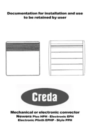
Creda CPH10T Manual


Læs gratis den danske manual til Creda CPH10T (4 sider) i kategorien Varmeapparat. Denne vejledning er vurderet som hjælpsom af 3 personer og har en gennemsnitlig bedømmelse på 4.4 stjerner ud af 2 anmeldelser. Har du et spørgsmål om Creda CPH10T, eller vil du spørge andre brugere om produktet?

Side 1/4
Installation and Operating Instructions
Creda Compact Heater
300003040 Issue 4
THESE INSTRUCTIONS SHOULD BE READ CAREFULLY AND RETAINED FOR FUTURE REFERENCE
Model(s) A B CWatt
CPH05T 500 425mm 400mm 115mm
CPH10T 1000 525mm 400mm 115mm
CPH15T 1500 625mm 400mm 115mm
CPH24T 2400 925mm 400mm 115mm
Dimensions
IMPORTANT SAFETY ADVICE
When using electrical appliances, basic
precautions should always be followed to
reduce the risk of re, electrical shock, and
injury to persons, including the following:
IMPORTANT - The wall bracket supplied with
the appliance must be used.
DO NOT use this heater in the immediate
surroundings of a bath, a shower or a swimming
pool.
IMPORTANT - If the heater is installed in a
room containing a bath or shower, it must be
so installed that switches and other controls
cannot be touched by a person using a bath
or shower.
WARNING - In order to avoid overheating, do
not cover the heater. Do not place material
or garments on the heater, or obstruct the
air circulation around the heater, for instance
by curtains or furniture, as this could cause
overheating and a fi re risk.
This heater carries the warning symbol
indicating that it must not be covered.
NEVER cover or obstruct in any way the heat
outlet slots at the top of the heater or the air
inlet slots in the base of the heater.
CAUTION - Some parts of this product can
become very hot and cause burns. Particular
attention has to be given where children and
vulnerable people are present.
This appliance can be used by children aged
from 8 years and above and persons with
reduced physical, sensory or mental capabilities
or lack of experience or knowledge if they
have been given supervision or instruction
concerning the use of the appliance in a safe
way and understand the hazards involved.
Children shall not play with the appliance.
Cleaning and user maintenance shall not be
carried out by children without supervision.
Children aged from 3 years and less than 8
years shall only switch on/off the appliance
provided that it has been placed or installed
in its intended normal operating position and
they have been given supervision or instruction
concerning the use of the appliance in a safe
way and understand the hazards involved.
Children aged from 3 years and less than 8
years shall not plug in, regulate and clean the
appliance or perform user maintenance.
If the supply cord is damaged it must be
replaced by the manufacturer or service agent
or a similarly quali ed person in order to avoid
a hazard.
WARNING:
Servicing and product
repairs should only be undertaken by the
manufacturer’s approved service agent or
a similarly quali ed person, using only exact
manufacturer approved spare parts.
IMPORTANT: The supply circuit to the heater
must incorporate a double pole isolating
switch having a contact separation of at least
3mm.
WARNING: Packaging should be disposed
of responsibly as the EPS used could be a
potential choking hazard for children.
WARNING: Do not locate the heater
immediately below a xed socket outlet or
connection box.
CAUTION: In order to avoid a hazard due to
inadvertent resetting of the thermal cut-out,
this appliance must not be supplied through
an external switching device, such as a timer,
or connected to a circuit that is regularly
switched on and off by the utility.
50mm (min)
‘A
‘B’
30mm
(min)
30mm
(min)
300mm
(min)
Shelf
Minimu
front
clearanc
Fig. 1
50mm
(min)
‘C’
Energy Related Product Directive
Type of heat output/ room temperature control
With electronic room temperature control Yes
Electronic room temperature control plus week
timer
Yes
With open window detection No
Model Identifi er(s):
CPH05T CPH10T CPH15T CPH20T CPH24T
Nominal heat
output
Pnom 0.5 kW 1 kW 1.5 kW 2 kW 2.4 kW
Height (mm)
400
Depth (mm)
115
Width (mm)
425 625525 925 925
Minimum heat
output (indica-
tive)
Pmin 0.5 kW 1 kW 1.5 kW 2 kW 2.4 kW
Maximum continu-
ous heat output
Pmax,c 0.5 kW 1 kW 1.5 kW 2 kW 2.4 kW
Auxiliary electricity Consumption
At nominal heat
output
elmax 0.00 0.00 0.00 0.00 0.00
At minimum heat
output
elmin 0.00 0.00 0.00 0.00 0.00
In standby mode elSB
<0.0005 <0.0005 <0.0005 <0.0005 <0.0005
This product complies with Lot20 of the Energy Ef ciency Directive (2015/1188)
General Information
This heater must be used wall-mounted. The necessary wall mounting brackets
are provided with the product as a standard. It should only be operated when
in the upright position as shown - see Fig.1. Before connecting the heater check
that the supply voltage is the same as that stated on the heater.
WARNING: THIS APPLIANCE MUST BE EARTHED
WARNING:- The electrical installation of this heater must be carried out by
a suitably qualifi ed or trained electrician, and be in strict accordance with
the current wiring Regulations BS 7671. The supply must be connected via a
switched fused spur with a fuse rated suitably for the appliances ex. Failure
to follow these instructions will mean that the manufacturer’s instructions have
not been adhered to. THERE ARE NO EXCEPTIONS.
Mains lead are coloured in accordance with the following code:
GREEN AND YELLOW: EARTH
BLUE: NEUTRAL
BROWN: LIVE
The heater is tted with a length of exible cable type H05VV-F size 3 x 1.5mm2
models for connection to the fi xed wiring of the premises through a suitable
connection box positioned adjacent to the heater. A means for disconnection
must be incorporated in the xed wiring of the premises in accordance with
the current wiring regulations. Products that are supplied without a plug are
for installation into the fi xed wiring of the property, via a suitable double pole
switched fused spur with a fuse rated suitably for the appliances fl ex.
WARNING: This heater must not be connected to the electricity supply via an
external switching device.
Electrical Connection
STEP 1: The wall bracket can be used as a measuring device for placing the
heater on the wall. Mark the location for the two bottom screws (A-A)
and fasten the two screws in the wall - .see Fig. 2
STEP 2: screws (A-A). Then fasten the wall bracket with the top screws. Place
the heater on the wall bracket (1) and click the heater onto the top
catches (2).
10
10 cm
Fig. 2
Control Unit
Copy
Advance
Automatic Operation
Time block off
Time block on
Manual Operation
Program no. (1-4)
Weekday
Setting the time
Heating operation off
Heating operation on
Key lock
The heater is supplied with a confi gurable electronic control, consisting of a display,
a LED screen and ve membrane buttons. The control unit is located on the right
hand side of the panel.
The set functions and values are shown on the display.
The LED lights up red when heating ON
Wall Mounting
IMPORTANT - The radiator must only be mounted using the kit supplied
Value down/up
Set program
Select Operating Mode
Save Entry
IMPORTANT - Pull out the battery isolator strap before connecting the
product. Please dispose of careful as this may be a choking hazard.
1
2
Fig. 3
1
2


Produkt Specifikationer

Mærke: Creda
Kategori: Varmeapparat
Model: CPH10T

Har du brug for hjælp?

Hvis du har brug for hjælp til Creda CPH10T stil et spørgsmål nedenfor, og andre brugere vil svare dig


Varmeapparat Creda Manualer

Creda

Creda CPH10T Manual

25 August 2025
Creda

Creda CPH20T Manual

25 August 2025
Creda

Creda CPH05T Manual

25 August 2025
Creda

Creda TSR18MW Manual

29 August 2024
Creda

Creda CEP1500E Manual

29 August 2024
Creda

Creda TSRE150 Manual

29 August 2024
Creda

Creda CEP2000E Manual

29 August 2024
Creda

Creda CEP075E Manual

29 August 2024
Creda

Creda COR15TS Manual

29 August 2024
Creda

Creda TPRIII 500M Manual

29 August 2024

Varmeapparat Manualer

Nyeste Varmeapparat Manualer