GLS-LCCT
Crestron SolarSync™ Photosensor
Installation Guide
Description
The GLS-LCCT SolarSync™ Photosensor measures the correlated color temperature
(CCT) and luminosity (lux) of outdoor, natural sunlight. Measurements from the sensor are
relayed to the Crestron
®
control system, which adjusts indoor lighting to match outdoor
lighting conditions.
Additional Resources
Visit the product page on the Crestron website (www.crestron.com)
for additional information and the latest rmware updates. Use a QR
reader application on your mobile device to scan the QR image.
Installation
The GLS-LCCT is designed to be mounted outdoors (on a roof) or indoors (beneath
a skylight). When determining the mounting location, provide the GLS-LCCT with an
unobstructed view of the sky. Use a 1/2 inch knockout (0.885 inch (22.5 mm) actual hole
size) when mounting.
WARNING: To avoid personal injury and equipment damage, consider the following
when mounting the GLS-LCCT outdoors:
• Secure the GLS-LCCT to an IP67 or better J-box to ensure that the enclosure
remains waterproof.
• Use a CSP-LSP Lighting Strike Protector to prevent personal injury during
a lighting strike or damage to the control system and other devices on the
Cresnet
®
network.
• Mount the CSP-LSP inside the building at the point where the Cresnet network
cable enters the building. The CSP-LSP must be properly grounded.
• For installation, wiring, and operation of the CSP-LSP, refer to the CSP-LSP
Installation and Operation Guide (see www.crestron.com/manuals).
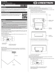
Install the GLS-LCCT:
1. Disconnect power to the system.
2. Seat the o-ring in the groove on the bottom of the sensor.
3. Thread the wire pigtail and the threaded nipple through the knockout. Ensure that the
sensor sits ush with the J-box.
4. Secure the sensor to the J-box using a 1/2-14 NPT locknut. Tighten the locknut to
ensure a proper seal with the J-box.
1/2 inch knockout
(0.885 inch (22.5 mm)
actual hole size)
IP67 or better box
1/2-14 NPT nut
GLS-LCCT
5. Make the Cresnet network connections inside the box using the provided
connectors.
6. Reconnect power to the system.
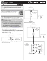
Wiring Diagram - Indoor Mounting Location
Cresnet to the
control system
Wiring the
GLS-LCCT inside
the J-box.
Terminal Wire Color
24: Red
Y: White
Z: Blue
G: Black
Wiring Diagram - Outdoor Mounting Location
Cresnet to the
control system
Wiring the
GLS-LCCT to the
CSP-LSP inside the
building space.
To a properly
grounded point in
the building.
Wiring the
GLS-LCCT inside
the IP67 or greater
box.
Terminal Wire Color
24: Red
Y: White
Z: Blue
G: Black