Crestron MMX-6-USB Manual
Læs gratis den danske manual til Crestron MMX-6-USB (24 sider) i kategorien Blandekonsol. Denne vejledning er vurderet som hjælpsom af 70 personer og har en gennemsnitlig bedømmelse på 4.7 stjerner ud af 35.5 anmeldelser.
Har du et spørgsmål om Crestron MMX-6-USB, eller vil du spørge andre brugere om produktet?
Produkt Specifikationer

| Mærke: | Crestron |
| Kategori: | Blandekonsol |
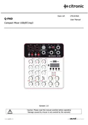
| Model: | MMX-6-USB |
| Vekselstrømsindgangsspænding: | 100-240 V |
| Vekselstrømsindgangsfrekvens: | 50 - 60 Hz |
| Bredde: | 178 mm |
| Dybde: | 178 mm |
| Højde: | 35 mm |
| Vægt: | 545 g |
| Produktfarve: | Sort |
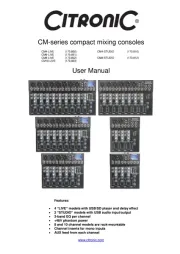
| USB-port: | Ja |
| Frekvensområde: | 20 - 20000 Hz |
| DC-in-stik: | Ja |
| Mac kompabilitet: | Ja |
| Videofunktion: | Ingen |
| Understøttede Windows-operativsystemer: | Ja |
| Understøttede Mac-operativsystemer: | Ja |
| USB-stik type: | Mini-USB B |
| Antal kanaler: | 6 kanaler |
| Fantomstrøm: | 48 V |
| Krydstale (1 kHz): | 70 dB |
| Prøvetagningshastighed: | 48 kHz |
| Digital lydbehandling: | 16 Bit |
| DJ mixer: | Ingen |
| Sikring: | 0.5 A |
Har du brug for hjælp?
Hvis du har brug for hjælp til Crestron MMX-6-USB stil et spørgsmål nedenfor, og andre brugere vil svare dig
Blandekonsol Crestron Manualer

Blandekonsol Manualer
- Yamaha
- Shure
- Efbe-Schott
- Arendo
- Phonic
- Radial Engineering
- ART
- Bifinett
- Soundcraft
- IMG Stageline
- Domo
- Concept
- Dangerous Music
- Monacor
- Chandler
Nyeste Blandekonsol Manualer