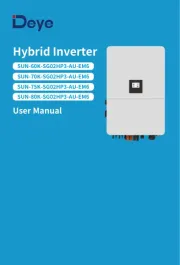
Deye SUN-80K-SG02HP3-EU-EM6 Manual

Deye Ikke kategoriseret SUN-80K-SG02HP3-EU-EM6

Læs nedenfor 📖 manual på dansk for Deye SUN-80K-SG02HP3-EU-EM6 (61 sider) i kategorien Ikke kategoriseret. Denne guide var nyttig for 12 personer og blev bedømt med 5.0 stjerner i gennemsnit af 6.5 brugere

Side 1/61
R
Hybrid Inverter
User Manual
SUN-80K-SG02HP3-EU-EM6
SUN-60K-SG02HP3-EU-EM6
SUN-75K-SG02HP3-EU-EM6
1. Safety Introductions
2. Product instructions
2.1 Product Overview
�������������������
�������������������
2.2 Product Size
01-02
02-06
Contents
2.3 Product Features
2.4 Basic System Architecture
2.5 Product handling requirements
�����������������������
3. Installation
3.1 Parts list
3.2 Mounting instructions
3.6 PV Connection
3.5Grid connection and backup load connection
06-30
3.7 Meter or CT installation
3.8 Earth Connection(mandatory)
3.9 Data logger connection
3.10 Wiring diagram with neutral line grounded
3.13 Typical application diagram of diesel generator
3.11 Wiring diagram with neutral line ungrounded
3.12 Typical application diagram of on-grid system
3.14 Three phase parallel connection diagram
�������������������������46-476. Mode
5.6 Battery Setting Menu
5.7 System Work Mode Setup Menu
5.8 Grid Setting Menu
5.9 Generator Port Use Setup Menu
5.10 Advanced Function Setup Menu
5.11 Device Info Menu
�����������������������
�������������������
4. OPERATION
4.1 Power ON/OFF
4.2 Operation and Display Panel
5. LCD Display Icons
5.1 Main Screen
5.2 Detail page
31
32-46
5.4 System Setup Menu
5.5 Basic Setting Menu
5.3 Curve Page-Solar & Load & Grid
������������������
������������������������
7. Warranty
9. Datasheet
47-48
54-55
�����������������������10. Appendix I 55-56
�����������������������11. Appendix II 57
���������������12. EU Declaration of Conformity 57-58
������������������������
8. Troubleshooting 48-53
3.3 Function port definition
3.4 Battery connection
- 01 -
About This Manual
This manual provides information and guidelines for the installation, operation, and
maintenance of the SUN-(60-80)K-SG02HP3-EU-EM6 inverter. Please note that it does not
contain comprehensive information about the photovoltaic (PV) system.
How to Use This Manual
Before undertaking any operation involving the inverter, it is crucial to thoroughly read this manual
and any associated documents. Ensure that these documents are stored safely and are readily
accessible at all times.
Please be aware that the contents of this manual may undergo periodic updates or revisions as a
result of ongoing product development. Consequently, the information contained herein is subject
to change without prior notice. The latest manual can be acquired via service@deye.com.cn
1. Safety Introductions
Labels description
Label Description



󾙔󾙒󾙒󾙔󾙛󾙘










󾙗
󽗿
2. Product Introductions
This is a multifunctional inverter, combining functions of inverter, solar charger and battery
charger to offer uninterruptible power support with portable size. Its comprehensive LCD display
offers user configurable and easy accessible button operation such as battery charging, AC/solar
charging, and acceptable input voltage based on different applications.
· This chapter contains important safety and operating instructions. Read and keep this manual
for future reference.
· Before using the inverter, please read the instructions and warning signs of the battery and
corresponding sections in the instruction manual.
· Do not disassemble the inverter. If you need maintenance or repair, take it to a professional
service center.
· Improper reassembly may result in electric shock orre.
· To reduce risk of electric shock, disconnect all wires before attempting any maintenance or
cleaning. Turning off the unit will not reduce this risk.
· Caution: Only qualified personnel can install this device with battery.
· Never charge a frozen battery.
· For optimum operation of this inverter, please follow required specification to select appropriate
cable size. It is very important to correctly operate this inverter.
· Be very cautious when working with metal tools on or around batteries. Dropping a tool may
cause a spark or short circuit in batteries or other electrical parts, even cause an explosion.
· Please strictly follow installation procedure when you want to disconnect AC or DC terminals.
Please refer to "Installation" section of this manual for the details.
· Grounding instructions - this inverter should be connected to a permanent grounded wiring
system. Be sure to comply with local requirements and regulation to install this inverter.
· Never cause AC output and DC input short circuited. Do not connect to the mains when DC
input short circuits.
- 02 -
2.1 Product Overview
1: LCD display
2: Function buttons
4: DC switch
3: Power on/off button
5: Meter port
6: Parallel port
7: CAN port
8: DRM port
9: BMS port
10: RS485 port
11: Generator input
12: Grid
17: WiFi Interface
16: Battery input
14: Load
13: Function port
15: PV input
- 03 -
15
16
17
1
2
3
4
6
5
7
8
10
9
11
12
13
14
- 04 -
2.2 Product Size
Inverter Size
338.00�mm
314.50�mm
606.00�mm
927.00�mm
985.26�mm
4Φ 14
518.00�mm
270.00�mm274.50�mm
314.00�mm
180. 00�mm
- 05 -
2.3 Product Features
- 230V/400V Three phase Pure sine wave inverter.
- Self-consumption and feed-in to the grid.
- Auto restart while AC is recovering.
- Programmable supply priority for battery or grid.
- Programmable multiple operation modes: On grid, off grid and UPS.
- Configurable battery charging current/voltage based on applications by LCD setting.
- Configurable AC/Solar/Generator Charger priority by LCD setting.
- Compatible with mains voltage or generator power.
- Overload/over temperature/short circuit protection.
- Smart battery charger design for optimized battery performance
- With limit function, prevent excess power overflow to the grid.
- Supporting WIFI monitoring and have 3 or 4 built-in MPP Trackers, 1 MPP Tracker can
connect 2 PV strings.
- Smart settable three stages MPPT charging for optimized battery performance.
- Time of use function.
- Smart Load Function.
2.4 Basic System Architecture
The following illustration shows basic application of this inverter.
It also includes following devices to have a complete running system.
- Generator(Fro off-grid mode)or Utility Grid
- PV modules
Consult with your system integrator for other possible system architectures depending on your
requirements.
This inverter is designed to power a range of appliances commonly found in homes and offices,
including motor type appliances like refrigerators and air conditioning units. Before use, it's
advisable to verify appliance compatibility with this inverter.
GridBackup Load*
Cloud services
On-Grid Home Load
GeneratorGrid-connected InverterSmart Load
Battery
Solar
CT
AC cable DC cable
WiFI
LAN
GPRS/4G
OR OR
*Connected to the LOAD port
computer
phone
- 06 -
3. Installation
3.1 Parts List
Check the equipment before installation. Please make sure nothing is damaged in the package.
You should have received the items in the following package:
Wall mounting bracket x1
Hybrid inverter
x1 Communication cable x2
L-type Hexagon wrench
x1
Stainless steel anti-collision
bolt M12×60
x4
User
manual
User manual x1 Data logger(optional) x1
Meter(optional)
x 1
Three -Phase Smart Meter
SET ESC
transport
2.5 Product handling requirements
CAUTION:
Improper handling may cause personal injury!
· Arrange an appropriate number of personnel to carry the inverter according to
its weight, and installation personnel should wear protective equipment such
as anti-impact shoes and gloves.
· Placing the inverter directly on a hard ground may cause damage to its metal
enclosure. Protective materials such as sponge pad or foam cushion should be
placed underneath the inverter.
· Move the inverter by one or two people or by using a proper transport tool.
· Move the inverter by holding the handles on it. Do not move the inverter by
holding the terminals.
Lift the inverter out of the packaging box and transport it to the designated installation location.
Sensor Clamp
x 3
- 07 -
3.2 Mounting instructions
Installation Precaution
This Hybrid inverter is designed for outdoor use(IP65), Please make sure the installation site
meets below conditions:
Excessive heat buildup, heavy rainfall or water pooling, can impact the performance and
longevity of the inverter. Before connecting all wires, please take off the metal cover by
removing screws as shown below:
· Not in direct sunlight, rain exposure, snow laying up during installation and operation.
· Not in areas where highly flammable materials are stored.
· Not in potential explosive areas.
· Not directly expose to the cold air to avoid condensation inside the inverter casing .
· Not near the television Antenna or antenna cable.
· Not higher than altitude of about 2000 meters above sea level.
· Not in environment of precipitation or humidity(>95%)
DC+/DC- Plug connectors
including metal terminal
xN
Battery Plug connectors
accessories x4
T-type wrench
x1
Stainless steel mounting
screws M4*12 x9
Hexagon socket flat
head screw x2
Solar Photovoltaic
Connector Special
Spanner x1
7,*8,*9
Magnetic ring for AC
wires x3
(80×50×25 mm)
4,5,6
Magnetic ring for CT x3
(31×29×19 mm)
Magnetic ring for
commuication cable of
BMS and Meterx3
(23×33×15 mm)
1,2,3
Matching Resistor x1
*8 &*9 are placed on the top of the
EPE material upper cover
1,2,3 : 23×33×15 mm
4,5,6 : 31×29×19mm
7,8,9 :80×50×25 mm
Packing box of magnetic ring
1 2 3
4 5 6
7
- 08 -
Considering the following points before selecting where to install:
· Please select a vertical wall with load-bearing capacity for installation, suitable for installation
on concrete or other non-flammable surfaces, installation as follows.
· Install this inverter at eye level in order to allow the LCD display to be read at all times.
· The ambient temperature is recommeded to be between -40~60℃ to ensure optimal operation.
· Be sure to keep enough distance between other objects and the inverter surfaces as shown in the
diagram to guarantee sufficient heat dissipation and have enough space for removing wires.
Installations Tools


    



    󾙖󾙘 

    
󾙅󾙓󾙓󾙒󾙒󾙖󾙗 
- 09 -
For a proper ventilation of the inverter and avoid overheating, allow a clearance of approximately
50 cm around the inverter and at least 100 cm to the front as it can be seen at the picture below.
Mounting the inverter
Remember that this inverter is heavy! Please be careful when lifting out from the package.
Choose the recommend drill head(as shown in below pic) to drill 4 holes on the wall,
62-70mm deep.
1. Use a proper hammer to fit the expansion bolt into the holes.
2. Screw out the nuts of the expansion bolts, align the holes of the mounting bracket with the 4
expansion bolts, and then push in the mounting bracket, tighten the nuts of expansion bolts.
3. Mount the inverter on the mounting bracket and use screws to fix the inverter with mounting
bracket.
500mm
500mm
Inverter Moun�ng bracket installa�on
Size: M12×60
- 10 -
1 2 3 4 5 6 1 2 3 4 5 6 7 8 9 10 1112
Meter: for energy meter communication.
Parallel_1: Parallel communication
port 1.
Parallel_2: Parallel communication
port 2 . (Parallel A and B are
same and have no particular orders)
CAN: reserved.
DRM: Logic interface for AS/
NZS 4777.2:2020.
BMS1: BMS port for battery
communication port 1.
BMS2: BMS port for battery
communication port 2.
RS485: RS485 port.
CT -L2
CT -L3
CT -L1
Gen start-up
N/O Relay
Parallel_1 Parallel_2Meter CAN DRM BMS1 BMS2 RS485
GS (diesel generator startup signal)
relay
coil
open
contact
G S
3.3 Func�on port defini�on
CN1 CN2
Inverter
CT-L1 CT-L2 CT-L3
SHUT DOWN
B B
CN1:
CT-L1 (1,2): current transformer (CT-L1) for"zero
export to CT"mode clamps on L1 when
in three phase system.
CT-L2 (3,4): current transformer (CT-L2) for"zero
export to CT"mode clamps on L2 when
in three phase system.
CT-L3 (5,6): current transformer (CT-L3) for"zero
export to CT"mode clamps on L3 when
in three phase system.
If the secondary current of CT are within the range of
1A-5A, use terminals 1-6.
CN2:
G-start (1,2): dry contact signal for startup the diesel generator.
When the "GEN signal" is active, the open contact (GS) will
switch on (no voltage output).
DRY-1 (3,4): Dry contact output. When the inverter is in
off-grid mode and the "signal island mode" is checked,
the dry contact will switch on.
DRY-2 (5,6): reserved.
RSD+,RSD- (7,8): When battery is connected and the
inverter is in "ON" status, it will provide 12Vdc.
SHUT DOWN (9,10,11,12): if the terminal "B" & "B" (9&10)
is short-circuited with wire connection, or there’s 12Vdc
input at the terminal "+ "& "- " (11&12), the inverter will
give alarm (F22) and shutdown immediately.
DIP switch:For
communication setting
of parallel system.
Thread the end of the CT's wires through
the magnetic ring � and wrap the wires
around it five lap. Fix the magnetic ring
near the wiring terminals, as shown in the
above diagram. Repeat this operation for
the other two CTs.
- 11 -
4 6
5
- 12 -
3.4 Battery connection
For safe operation and compliance, a separate DC over-current protector or disconnect device is
required between the battery and the inverter. In certain applications, a disconnect switch may
not be necessary, but it is always essential to have DC overcurrent protection in place. Refer to
the typical amperage in the page 28 for the required fuse or circuit breaker size.
Pic 3.1 BAT+ plug connector Pic 3.2 BAT- plug connector
Orange
Safety Hint:
Please use approved DC cable for battery system.
Model Range Recommended value
Cross section(mm )
60/75/80kW 4AWG 16mm2
Chart 3-2
The steps to assemble the battery plug connectors are listed as follows:
a) Pass the cable through the terminal, as shown in Pic 3.3.
Pic 3.3
Black
- 13 -
b) Put on the rubber ring, as shown in Pic 3.4.
Pic 3.4
d) Fasten terminal with a bolt, as shown in Pic 3.6.
Pic 3.6
e) Fasten the terminal with outer cover, as shown in Pic 3.7.
Pic 3.7
c) Crimp the metal terminal, as shown in Pic 3.5.
Pic 3.5
Hydraulic pliers
BMS connection
Thread the BMS communication cable
through the magnetic ring 1,2 and wrap
it around the magnetic ring four times.
1,2
- 14 -
3.5 Grid connection and backup load connection
· Before connecting to the grid, a separate AC breaker must be installed between the inverter
and the grid, and also between the backup load and the inverter.This will ensure the inverter
can be securely disconnected during maintenance and fully protected from over current.Check
the recommended values in the following tables according to local regulations in each country.
The recommended specifications for AC breakers here are based on the Max.Continuous AC
passthrough current of inverter, you can also choose the AC breaker of backup side according
to the actual total operating current of all the backup loads.
· There are three terminal blocks with "Grid" "Load"and "GEN" markings. Please do not misconnect
input and output connectors.
Grid connection and backup load connection (Copper wires) (bypass)
Model
60/75/80kW
Wire Size
4/0AWG
Cross section(mm )
2
95
Torque value(max)
20.3Nm
Grid connection and backup load connection (Copper wires)
Note:
In final installation,breaker certified according to IEC 60947-1 and IEC 60947-2
shall be installed with the equipment.
Model
60/75/80kW
Recommended
AC breaker
240A
AC Breaker for backup load
AC Breaker for grid
All wiring must be performed by a qualified personnel.It is very important for
system safety and efficient operation to use appropriate cable for AC input
connection. To reduce risk of injury, please use the proper recommended cable
as below. There are two tables below, the first table recommends cable specififi-
cations based on bypass current(Max.Continuous AC passthr ough), and the
second table is based on Max.Three-phase Unbalanced Output Current .
Model
60/75/80kW
Recommended
AC breaker
240A
1. Before making Grid, load and Gen port connection, be sure to turn off AC breaker or
disconnector first.
2. Strip the insulation of AC wires by about 10mm, insert AC wires according to polarities indicated
on the terminal block and tighten the terminals. Be sure to connect corresponding N wires and PE
wires to related terminals as well.
Please follow below steps to implement Grid, load and Gen port connection:
Chart 3-3 Recommended Size for AC wires
Model
60kW
80kW
Wire Size
4/0AWG
Cross section(mm )
2
95
Torque value(max)
20.3Nm
75kW 954/0AWG 20.3Nm
4/0AWG 20.3Nm95
- 15 -
GRID
LOAD E-BAR
E-BAR
GEN
NL1 L2
L3
PE
Thread the end of wires through the
magne�c ring 7 and connect these wires to
the terminals of LOAD port corresponding to
the indica�on of polarity.
LOAD GEN
GRID
Thread the end of wires through the
magne�c ring 8 and connect these wires to
the terminals of GEN port corresponding to
the indica�on of polarity.
78
Thread the end of wires through the
magne�c ring 9 and connect these wires to
the terminals of GRID port corresponding to
the indica�on of polarity.
9
78
9
3.6 PV Connection
3. Make sure all the wires are securely and completely connected.
Before connecting to PV modules, please install a separately DC circuit breaker between
inverter and PV modules. It is very important for system safety and efficient operation to
use appropriate cable for PV module connection.
Be sure that AC power source is disconnected before attempting to wire it to the
unit.
To avoid any malfunction, do not connect any PV modules with possible leakage
current to the inverter. For example, grounded PV modules will cause leakage
current to the inverter. When using PV modules, please ensure the PV+ & PV-
of solar panel is not connected to the system ground bar.
It is requested to use PV junction box with surge protection. Otherwise, it will
cause damage on inverter when lightning occurs on PV modules.
4. Some appliances, such as air conditioners and refrigerators, may need a time delay before
recconneting them after a power outage. This delay allows the refrigerant gas to stabilize and
prevents potential damage. Check if your appliance has a built-in time-delay function before
connecting it to our inverter. Examples of appliances that may require a delay include:
Air conditioners: Balancing refrigerant gas.
Refrigerators: Stabilizing the compressor.
Freezers: Allowing the cooling system to balance.
Heat pumps: Protecting against power fluctuations.
This inverter will protect your appliances by triggering an overload fault if no time delay is
present. However, internal damage may still occur. Refer to the manufacturer's documenta-
tion for specific time-delay requirements.
- 16 -
3.6.1 PV Module Selection:
3.6.2 PV Module Wire Connection:
When selecting proper PV modules, please be sure to consider below parameters:
1) Open circuit Voltage (Voc) of PV modules can not exceed max.PV Input Voltage of
inverter.
2) Open circuit Voltage (Voc) of PV modules should be higher than min.PV Input Voltage of inverter.
3) The PV modules used to connected to this inverter shall be Class A rating certified according
to lEC 61730.
- 17 -
1. Switch the Grid Supply Main Switch(AC)OFF.
2. Switch the DC lsolator OFF.
3. Assemble PV input connector to the inverter.
Safety Hint:
Before connecting to inverter, please make sure that the open circuit voltage of
PV strings haven't exceeded the max.PV input voltage of the inverter.
Safety Hint:
Before connection, please make sure the polarity of PV array matches the
"DC+" and "DC-" symbols.
Pic 5.1 DC+ male connector Pic 5.2 DC- female connector
Chart 3-5
PV Input Voltage
Inverter Model
PV Array MPPT Voltage Range
No. of MPP Trackers
No. of Strings MPP Tracker
650V (180V-1000V)
150V-850V
2+2+2+2+2+2
6
60kW 80kW75kW
- 18 -
Safety Hint:
Please use approved DC cable for PV system.
Cable type Range Recommended value
Cross section(mm )
Industry generic PV cable
(model: PV1-F)
2.5-4
(12-10AWG) 2.5(12AWG)
The steps to assemble the PV connectors are listed as follows:
a) Strip the insulation of the PV wire by 7 mm, disassemble the cap nut of the connetctor,
thread one PV wire through the cap nut of the connector (see Pic 5.3). Repeat this operation
with all the PV wires, paying special attention to the polarity of the connector.
b) Crimping metal terminals with crimping pliers , as shown in Pic 5.4.
c) Insert the contact pin to the top part of the connector and completely tighten the cap nut to
the top part of the connector, as shown in Pic 5.5.
Pic 5.3 Disassemble the connector cap nut
Pic 5.4 Crimp the contact pin to the wire
Chart 3-6
7mm
7mm
Hydraulic pliers
-19 -
Pic 5.5 connector with cap nut screwed on
d) Finally insert the PV connectors into the positive and negative PV inputs of the inverter, as
shown in Pic 5.6.
Pic 5.6 DC input connection
Warning:
Warning:
Please use its own DC power connector from the inverter accessories. Do not
interconnect the connectors of different manufacturers. The Isc current of PV
modules should not exceed the Max.PV Isc current of this inverter. If exceeds,
it may damage the inverter and is not covered by Deye's warranty.
When operating the PV strings, be aware that sunlight exposure can generate high
voltages in the PV strings. Avoid contact with exposed electrical connecters or
terminals to prevent electrical shock or injury. For safety, it is best to operate the
PV strings at night or when PV modules are not exposed to sunlight. If daytime
operation is necessary, cover the PV modules to minimize sunlight exposure and
prevent high voltage generation. Remember to turn off the DC breaker or switch
before performing any maintenance or adjustments. Do not turn off the DC
breaker or switch when high voltage or high current is present to avoid damage or
hazards. Prioritize personal safety.
- 20 -
1 2 3 4 5 6
C -L1 CT-L2 CT-L3
White wire Black wire
CT
Arrow�pointing
to�inverter
*Note:When taking power from the utility grid, if the grid power displayed
on the LCD screen is indeed negative, please adjust the installation direction
of the CTs.
Grid
N
PE
L1
L2
L3
CT1
CT2
CT3
Inverter
GRID
NL1 L2
L3
3.7 Meter or CT installation
3.7.1 CT connection
There are three selectable installation methods to measure the power consumption or to ensure zero power
export to grid. The default installation method is to use the CTs(300A/5A) that come with the packaging
box. When the distance between the AC distribution box and the hybrid inverter exceeds 10 meters, which
means that the wire length of the CT needs to exceed 10 meters, it is recommended to use a smart meter
instead of three CTs. In addition, in a parallel system, if the current to be measured is greater than 300 A, the
default three CTs also need to be replaced with smart meters or larger CTs. Please contact the Deye support
team to confirm which specification of CT or smart meter to use.
- 21 -
L1
L2
L3
N
PE
RS485A
RS485B
Three-Phase Smart Meter
SET ESC
1 74 10
2524
3
96 10
CHINT meter
Three-Phase Smart Meter
SET E SC
1 74 10
2524
3 96 10
RS 485
CHNT DTSU666
(3,6,9,10)
(1,4,7,10)
L1
L2
L3
Grid
Inverter
GRID
Parallel_1 Parallel_2Meter
NL1 L2
L3
L1
L1
L2
L2
L3
L3
N
N
RS485A
RS485B
Grid
Eastron meterEastron SDM630-Modbus V2
RS 485
RS 485 B RS 485 A
B A G
(5,6,7,8)
(1,2,3,4)
1 2 3 4
L1
L2
L3
5 6 7 8
GND
Eastron
5 6 7 8
L1
L2
L3
Eastron
5 6 7 8
Inverter
PE
GND
GRID
Parallel_1 Parallel_2Meter
NL1 L2
L3
3.7.2 Meter connection without CTs
There are two kinds of smart meter, one is passthrough smart meter, and the other is Mutual inductance
smart meter with CTs. The smart meter brands that Deye inverters have been matched with include CHINT
and Eastron,The recommended models here are not all compatible models,It is recommended to
purchase smart meter from authorized distributors of Deye, otherwise it may not be able to be used due to
communication mismatch. The definition of the "Meter" port can be found in the Appendix part which is in
the end of this user manual.
- 22 -
Three-Phase Smart Met er
SET ESC
7
2524211917161413
3 96 10
GRID
Parallel_1 Parallel_2Meter
Inverter
L1
L2
L3
N
PE
Grid
AC Breaker
AC Breaker Home Load
L1
L3
N
PE
L2
CT1
CT2
CT3
RS485A RS485B
NL1 L2
L3
Note: the arrow direc�on
towards the inverter
Three-Phase Smart Meter
SET ESC
2524211917161413
3 96 10
CHINT meter
RS 485
CHNT DTSU666
(3,6,9,10)
3 13 146 9 10 16 1719 21
Phase B current =5.001A
Phase C current =5.002A
Phase A current =5.000A
L1
L2
L3
PIN 13,16,19 White cable of the CT
PIN 14,17,21: Blue cable of the CT
White line
White line
White line
Blue line
Blue line
Blue line
230/400V,3~
250A/50mA
50/60Hz
3.7.3 Meter connection with CTs
Note: the arrow direc�on
towards the inverter
- 23 -
Black line
Black line
Black line
Red line
Red line
Red line
GRID
Parallel_1 Parallel_2Meter
Inverter
L1
L2
L3
N
PE
Grid
AC Breaker
AC Breaker Home Load
L1
L3
N
PE
L2
CT1
CT2
CT3
Eastron meter
Eastron SDM630MCT
1 2 3 4 5 6
L1
L2
L3
N
P1P2
S1S2
P2 P1
S1S 2
P1P2
S1S2
3 PHASE 4 WIRE
15 1617 18 19 20
Grid voltage
sampling
Auxiliary
power supply
Current inputs
RS 485
RS 485 A RS 485 B
1 4 1 3 1 2
GND
1 2 3 4 5 6 7 8
9 1 0 1 1 12 1 3 1 4 15 16 1 7 18 1 9 2 0
P
M
E
U/I
ESC
Eastron
meter
NA LA L1 L2 L3 N
S1 S2 S1 S2 S1 S2
1 2 3 4 5 6 7 8
9 1 0 1 1 1 2 1 3 1 4 1 5 1 6 1 7 1 8 1 9 2 0
P
M
E
U/I ESC
Eastron
RS485A
RS485B
GND
NL1 L2
L3
- 24 -
Meter connection
3
Thread the meter communication cable
through the magnetic ring 3 and wrap
it around the magnetic ring four times.
- 25 -
3.9 Data logger connection
For the configuration of data logger, please refer to the user manual of data logger. Wi-Fi plug is
not the only option, If the installation location does not have Wi-Fi signal or the signal is weak,
you can also choose a data logger that communicates via other interfaces.
The conductor should be made of the same metal as the phase conductors.
3.8 Earth Connection(mandatory)
Ground cable shall be connected to ground plate on grid side, this prevents electric shock if the
original protective conductor fails.
Earth Connection (Copper wires) (bypass)
Model
60/75/80kW
Wire Size
0AWG
Cross section(mm )
2
50
Torque value(max)
20.3Nm
Earth Connection (Copper wires)
Warning:
Inverter has built-in leakage current detection circuit,The type A RCD can be
connected to the inverter for protection according to the local laws and regula-
tions.If an external leakage current protection device is connected, its operating
current must be equal to 10mA/KVA or higher, for this series of inverter it should
be 800mA or higher, otherwise inverter may not work properly.
Model
60kW
75kW
Wire Size
0AWG
Cross section(mm )
50
Torque value(max)
20.3Nm
0AWG 20.3Nm50
80kW 500AWG 20.3Nm
2
- 26 -
3.10 Wiring diagram with neutral line grounded
This diagram is an example for an application that neutral connects with the
PE in a distribution box.
For countries such as Australia, New Zealand, etc., please follow
local wiring regulations!
E-BAR
GEN
PORT
Load
CT
PE
AC Breaker
L1 L1
N N
L2
Load
PE or
L2
L3
L3
AC Breaker AC Breaker
L1
L1
L1
N
N
N
L2
L2
Grid
PE
L2
L3
PE
PE
L3
L1
N
L2
PE
L3
L3
AC Breaker
Hybrid Inverter
CT1
CT2
CT3
RCD
Home Loads
RCD
E-BAR
Grid
Battery
BMS
DC Breaker
PV
DC Breaker
Do not connect this terminal when the neutral
wire and PE wire are connected together.
Inverter case grounding N-BAR
E-N
Link
- 27-
3.11 Wiring diagram with neutral line ungrounded
This diagram is an example for an application in which neutral is separated from the
PE in the distribution box.
For countries such as China, Germany,the Czech Republic, Italy, etc., please follow local
wiring reguations!
E-BAR
Backup
Loads
CT
PE
L2 L2
L1 L1
L3
Backup
PE or
L3
N
PE
N
L2
L2
L2
L1
L1
L1
L3
L3
On-Grid
PE
L3
N
PE
N
N
Hybrid Inverter
CT1
CT2
CT3
RCD
Home Loads
RCD
E-BAR
Grid
Battery
BMS
Distribution box
800mA RCD (Recommended)
RCD
DC Breaker
Grouding screw hole in the
lower right corner
GEN
PORT
L1
N
L2
PE
L3
AC Breaker
PV
DC Breaker
- 28 -
L wireCAN N wire PE wire
BMS1 BMS2
Grid
Backup Load
Inverter
①DC
Breaker
②AC Breaker
③AC Breaker
④AC Breaker
Battery pack
Home Load
L1
L1
L2
L2
L3
L3
N
N
PE
PE
L1
L2
L3
N
PE
Ground
CT1 CT2
CT3
①�DC�Breaker�for�battery
SUN�60K�SG02HP3�EU�EM6:�300A�DC�breaker
SUN�75K�SG02HP3�EU�EM6:�300A�DC�breaker
SUN�80K�SG02HP3�EU�EM6:�300A�DC�breaker
②�AC�Breaker�for�backup�load
SUN�60K�SG02HP3�EU�EM6:�240A�AC�breaker
SUN�75K�SG02HP3�EU�EM6:�240A�AC�breaker
SUN�80K�SG02HP3�EU�EM6:�240A�AC�breaker�
③�AC�Breaker�for�grid
SUN�60K�SG02HP3�EU�EM6:�240A�AC�breaker
SUN�75K�SG02HP3�EU�EM6:�240A�AC�breaker
SUN�80K�SG02HP3�EU�EM6:�240A�AC�breaker
④AC�Breaker�for�home�load
Depends�on�household�loads
3.12 Typical application diagram of on-grid system
BMS1 BMS2
3.13 Typical application diagram of diesel generator
- 29 -
L wireCAN N wire PE wire
①DC
Breaker
Battery pack
Backup Load
L3
L2
L1
N
PE
Generator
GS (diesel generator startup signal)
relay
coil
open
contact
G S
G-start (1,2): dry contact signal for startup
the diesel generator.
Remotely control signal line
Inverter
③AC Breaker
②AC
Breaker
L3
L2
L1
N
PE
1 2 3 4 5 6 7 8 9 10 1112
SHUT DOWN
B B
Ground
①�DC�Breaker�for�battery
SUN�60K�SG02HP3�EU�EM6:�300A�DC�breaker
SUN�75K�SG02HP3�EU�EM6:�300A�DC�breaker
SUN�80K�SG02HP3�EU�EM6:�300A�DC�breaker
②�AC�Breaker�for�backup�load
SUN�60K�SG02HP3�EU�EM6:�240A�AC�breaker
SUN�75K�SG02HP3�EU�EM6:�240A�AC�breaker
SUN�80K�SG02HP3�EU�EM6:�240A�AC�breaker�
③�AC�Breaker�for�Generator�port
SUN�60K�SG02HP3�EU�EM6:�240A�AC�breaker
SUN�75K�SG02HP3�EU�EM6:�240A�AC�breaker
SUN�80K�SG02HP3�EU�EM6:�240A�AC�breaker
- 30 -
L wireCAN N wire PE wire
3.14 Three phase parallel connection diagram
Inverter
Master inverter Slave Inverter Slave Inverter
Parallel
Master
Slave
Modbus SN
02
Advanced Function
Paral.
Set3
EX_Meter For CT
Meter Select
0/3No Meter
Parallel
Master
Slave
Modbus SN
03
Advanced Function
Paral.
Set3
EX_Meter For CT
Meter Select
0/3No Meter
Parallel
Master
Slave
Modbus SN
Advanced Function
Paral.
Set3
EX_Meter For CT
Meter Select
0/3No Meter
01
Grid
Backup Load
Inverter
No.3
(slave)
Inverter
No.2
(slave)
Inverter
No.1
(master)
Battery pack
Home Load
L1 L2 L3NPE
L1
L2
L3
N
PE
CT
Arrow pointing
to inverter
Ground
Ground
Ground
Battery pack
Battery pack
CT1 CT2
CT3
Parallel_1 Parallel_2Meter CAN DRM BMS1 BMS2 RS485
①②③ DC Breaker for battery
SUN-60K-SG02HP3-EU-EM6: 300A DC breaker
SUN-75K-SG02HP3-EU-EM6: 300A DC breaker
SUN-80K-SG02HP3-EU-EM6: 300A DC breaker
⑤⑦⑨ AC Breaker for backup load
SUN-60K-SG02HP3-EU-EM6: 240A AC breaker
SUN-75K-SG02HP3-EU-EM6: 240A AC breaker
SUN-80K-SG02HP3-EU-EM6: 240A AC breaker
④⑥⑧ AC Breaker for grid port
SUN-60K-SG02HP3-EU-EM6: 240A AC breaker
SUN-75K-SG02HP3-EU-EM6: 240A AC breaker
SUN-80K-SG02HP3-EU-EM6: 240A AC breaker
⑩ AC Breaker for home load
Depends on household loads
Note: For the parallel system, the lead-acid battery and 'No Batt' mode are not supported.
All inverters connected in parallel must be the same model. Please use lithium battery which
is on the "Deye Approved Battery list".
Each inverter should have its own separate battery set.
Ensure that the DIP switches of each
hybrid inverter in the parallel system
are switched to the OFF state.
Note: The idle parallel ports of the first and last inverters
need to be plugged in with matching resistors.
OFF ON
Note: For the parallel system,
please choose the "Zero export to CT " mode.
4. OPERATION
4.1 Power ON/OFF
4.2 Operation and Display Panel
The operation and display panel, shown in below chart, is on the front panel of the inverter.
It includes four indicators, four function keys and a LCD display, indicating the operating status
and input/output power information.
Chart 4-1 LED indicators
LED Indicator
DC
AC
Normal
Alarm
Green led solid light
Red led solid light
PV Connection normal
Grid Connection normal
Inverter operating normal
Malfunction or warning
Messages
Chart 4-2 Function Buttons
Function Key
Esc
Up
Down
Enter
Description
To exit setting mode
To go to previous selection
To go to next selection
To confirm the selection
- 31 -
Once the system has been properly installed and the battery is connected to the inverter, follow
the steps below to turn on the inverter:
1. Turn all the breakers of the installation on.
2. Turn on the DC switches of the inverter and the power button of battery (If there is one battery
installed at the system), no matter the order.
3. Press the ON/OFF button (located on the left side of the inverter case) to turn on the inverter.
When a system connected to either PV or Grid (without battery) is switched on, the LCD will still
be lighted up displaying "OFF". In this situation, after switching ON/OFF button on, select "NO
batt" at the inverter settings to make the system work.
When turning off the inverter, please follow the following steps:
1. Turn off the AC breakers on Grid port, Load port and GEN port.
2. Press the ON/OFF button of hybrid inverter and turn off the DC breaker on battery side, then
turn off the power button of the battery.
3. Switch off the DC switches of the inverter.
5.1 Main Screen
5. LCD Display Icons
The LCD is touchscreen, below screen shows the overall information of the inverter.
01/19/2024 19:34:40
0.00
KW
-35.0
KW
35.1
KW
0.00
KW
0 80
0 80
0 80
0 80
Fri
ON
- 32-
1.The icon at the center of the screen indicates whether the system is under normal operation
or not, displaying "ON" for normal status or displaying a code like "Comm./F01-F64" for
communication errors or other errors. Please refer to the Error code list of alarms and errors in
chapter 8 to find out solutions about the error.
2.At the top-center of the screen is the date and local time that must be set during
commissioning.
3.System Setup Icon, Press this set button,you can enter into the system setup screen which
including Basic Setting, Battery Setting , Grid Setting, System Work Mode, Generator
Port Use, Advanced Function and Device info.
4.The main screen includes the icons for PV(left up), grid (right up), load (right bottom)
and battery (left bottom). It also displays the energy flow direction by moving dots. When the
power is approaching to a high level, the color on the panels will change from green to red,
showing vividly the system status on the main screen.
Some clarifications about the system status are as follows:
-PV power will always be positive.
-In single inverter system, load power will always be positive. In a parallel system, the load
power may be negative, which means that the other inverters supply power to this inverter
through the load port.
-A negative Grid power means energy being exported to the grid (sold), whereas positive means
energy being imported form the grid (purchased).
-Negative battery power means charge, positive means discharge.
0% 74%
5.1.1 LCD operation flow chart
Main Screen
Solar Page Solar Graph
Grid Graph
BMS Page
Load Graph
Battery Setting
System Work Mode
Grid Setting
Gen Port Use
Basic Setting
Advanced Function
Device info
Grid Page
Inverter Page
Battery Page
Load Page
System Setup
- 33 -
1166w
L1N: 221v 0w
L2N: 229v 1166w
L3N: 225v 0w
21w
150V
M1:0.00KW/ 0V/ 0.0A
M3:0.00KW/ 0V/ 0.0A
M5:0.00KW/ 0V/ 0.0A
M2:0.00KW/ 0V/ 0.0A
M4:0.00KW/ 0V/ 0.0A
M6:0.00KW/ 0V/ 0.0A
0.00KW
-0.41A
27.0C
150V
-0.41A
27.0C
1244w
50Hz
Load
Battery PV
Grid Inverter
L1N: 222v 0.8A
L2N: 229v 5.0A
L3N: 229v 0.9A
HM: LD:
-10W 28W
5W 1192W
0W 24W
-81w
50Hz
L1N: 222v 0.1A
L2N: 230v 0.1A
L3N: 223v 0.1A
INV_P:
-30W
-26W AC_T:
-25W 38.8C
0w 0w
5.2 Detail page
- 34 -
0W
Stand by
0.0Hz
Energy
CT2: 0W LD2 0W
CT1 0W LD1 0W
BUY
Today=0.0KWH
Total =8.60 KWH
Today=2.2KWH
Total =11.60 KWH
SELL
CT3: 0W LD3 0W
L1: 0V L2: 0V L3: 0V
Grid
This is Solar Panel detail page.
Press the "Energy "button will enter into the power
curve page.
Solar Panel Generation.
Voltage, Current, Power for each MPPT.
Daily and total PV production.
Power: 55W Today=0.5 KWH
Total =1.60 KWH
L1: 220V P1: 19W
L2: 220V P2: 18W
L3: 220V P3: 18W
Load
Energy
This is Grid detail page.
Press the "Energy " button will enter into the power
curve page.
Status, Power, Frequency.
BUY: Energy from Grid to Inverter,
L: Voltage for each Phase
CT: Power detected by the external current
sensors or smart meter.
LD: Power detected using internal sensors on
AC grid in/out port.
SELL: Energy from Inverter to grid.
This is Inverter detail page.
Power: 1560W
Energy
Today=8.0 KWH
Total =12.00 KWH
PV1-V: 286V PV1-I: 5.5A PV1-P: 1559W
PV2-V: 286V PV2-I: 5.5A PV2-P: 1559W
PV3-V: 286V PV3-I: 5.5A PV3-P: 1559W
PV4-V: 286V PV4-I: 5.5A PV4-P: 1559W
PV5-V: 286V PV5-I: 5.5A PV5-P: 1559W
PV6-V: 286V PV6-I: 5.5A PV6-P: 1559W
Solar
This is Load detail page.
When you check "Selling First" or "Zero export to
Load" on system work mode page, the information
on this page is about backup load which connect on
Load port of hybrid inverter.
When you check "Zero export to CT"on system work
mode page, the information on this page is including
backup load and home load.
Press the "Energy " button will enter into the power
curve page.
Load Power.
Voltage, Power for each Phase.
Daily and total Load consumption .
Click the icons on main screen of LCD display, you can enter the detail pages of "Solar",
"Inverter","Load","Grid" and "Batt".
DC/AC Inverter module:
Voltage, Current, Power of each Phase.
AC-T: Temperature near DC/AC inverter module.
- 35 -
Temp:25.0C
5.3 Curve Page-Solar & Load & Grid
2022-5-28
20%
1 3 5 7 9 11 13 15 17 19 21 23
40%
60%
80%
100%
3000W
Solar Power Production:Day
5-2022
400
0
05 10 15 20 25 30
800
1200
1600
2000
2000Wh
System Solar Power:Month
CANCEL Day Month Year TotalCANCEL Day Month Year Total
This is Battery detail page.
BATTERY DETAIL PAGE
Click the "Li-BMS" button on the lower right corner of
Battery detail page, you can enter the BMS page.
PV1-V: 0V PV1-I: 0.0A PV1-P: 0W
Power: 0W
Solar
Energy
Today=0.0 KWH
Total =0.00 KWH
In the main screen of LCD display, click the icons of "Solar", "Grid" and "Load", you can enter
the detail pages of Solar power, Grid power and Load consumption. Click the "Energy" button
on the lower right corner of these detail pages, you can enter the curve page. Using PV as an
example for illustration below.
01/19/2024 19:34:40
0.00
KW
-35.0
KW
35.1
KW
0.00
KW
0 80
0 80
0 80
0 80
Fri
ON
0% 74%
Battery 1
Stand by
SOC: 46%
U:631.7V
I:-0.09A
Power: -50W
Temp:27.0C
Battery 2
Stand by
SOC: 0%
U:0.0V
I:0.00A
Power: 0W
Temp:-100.0C
Batt
Li-BMS
Press the “Down” button, you can enter the
LiBms2 detail page
Battery
Voltage: 629.5V
Battery
capacity :100AH
LiBms1: Deye-HV
Battery
Current: 0.0A
Battery
Charge Voltage :691.2V
Battery
Temp: 27.0C
Charge
current limit :100A
SOC :46% SOH :100% Discharge current limit :100A
Battery SW: 0×1004
Battery HW: 0×3001
Alarms: 0×8000 0×0000
Request Force Charge
Li-BMS
Battery
Voltage: 0.0V
Battery
capacity :0AH
LiBms2: Not matched
Battery
Current: 0.0A
Battery
Charge Voltage :0.0V
Battery
Temp:-100.0C
Charge
current limit :0A
SOC :0% Discharge current limit :0A
Alarms: 0×0000 0×0000
Li-BMS
2022
40
1 2 3 4 5 6 7 8 9 10 11 12
80
120
160
200
KWh
System Solar Power:Year
CANCEL Day Month Year Total
TOTAL
400
020 20 20 20 20 20 20 20 20 20 20 20 20 20 20 20 20
16 18 20 22 24 26 28 30 32 34 36 38 40 42 44 46 48
800
1200
1600
2000
2000KWh
CANCEL Day Month Year Total
System Solar Power:Total
- 36-
5.4 System Setup Menu
System Work Mode
Battery
Setting
Grid Setting Gen Port
Use
Basic
Setting
System Setup
Device Info.
Advanced
Function
This is System Setup page.
Solar power curve for daily, monthly, yearly and total can be roughly checked on the LCD, for more
accuracy power generation, please check on the monitoring system. Click the up and down buttons
below the LCD screen to view the power curves of different time periods. The operation of checking
the grid power and load power is similar to the above operation.
5.5 Basic Setting Menu
Basic
Set1
Time Syncs Beep Auto Dim
24-Hour
Basic Setting
Year Month Day
Hour Minute
Lock out all changesFactory Reset
2019 03
09 15
17
Time Syncs: Enable the inverter to automatically
synchronize cloud platform time.
Beep: Used to turn on or off the beep sound in inverter's
alarm status.
Auto Dim: Used to automatically adjust the brightness of
the LCD display screen.
Factory Reset: Reset all parameters of the inverter.
Lock out all changes: Lock programmable parameters
to prevent them from being changed.
Factory Reset Password: 9999
PassWord
DELX--X--X--X
123
456
789
CANCEL 0 OK
Lock out all changes Password: 7777
When we select the "factory reset" or"Lock out all changes",
the system will require us to enter a password first to
confirm the operation.
1. Click the down arrow on the left side of the "Basic Set1"
page to enter the "Basic Set2" page;
2. On the "Basic Set2" page, you can set the display
language of the LCD screen as needed. Click the "UP" and
"DOWN" buttons below the LCD screen to switch
language options. The current available options are:
English, German, Polish, Hungarian, Spanish, Czech,
Ukrainian.
3. After switching to the desired language, click on the
check mark icon in the bottom right corner of the page to
save the settings.
Note:If the current LCD screen does not have a Basic
Set2 page, or if the language option on the Basic Set2
page does not include the language you need to set,
please contact the after-sales support team to update the
HMI firmware and language firmware package of the
inverter. After the update is completed, follow the above
steps to complete the setup.
Basic
Set2
Basic Setting
Language Select
Pack Version: 1004
Polish
- 37-


Produkt Specifikationer

Mærke: Deye
Kategori: Ikke kategoriseret
Model: SUN-80K-SG02HP3-EU-EM6

Har du brug for hjælp?

Hvis du har brug for hjælp til Deye SUN-80K-SG02HP3-EU-EM6 stil et spørgsmål nedenfor, og andre brugere vil svare dig