RTW 401 UN
02/08/A 1 5 21404 00 (FE)
Raumtemperaturregler im Flächenschalterrahmen für Unterputzmontage mit Bodentemperaturwächter
Room temperature controller for installation in a flush mounted switch frame with floor temperature thermostat
Thermorégulateur avec contrôleur de température du plancher pour la régulation de la température ambiante; installation encastrée dans un
cadre de recouvrement plat
Regulator temperatury pomieszczenia, do podtynkowego montażu w ramie powierzchownego przełącznika z czujnikiem temperatury podłogi
Sicherheitshinweis!
Dieses Gerät darf nur durch eine Elektrofachkraft geöffnet und gemäß dem entsprechenden Schaltbild im
Gehäusedeckel / auf dem Gehäuse / in der Bedienungsanleitung installiert werden. Dabei sind die beste-
henden Sicherheitsvorschriften zu beachten. Der Betrieb in der Nähe von Geräten, welche nichtAchtung!
den EMV-Richtlinien entsprechen, kann zur Beeinflussung der Gerätefunktionen führen. Nach der Installa-
tion ist der Betreiber, durch die ausführende Installationsfirma, in die Funktion und Bedienung der Rege-
lung einzuweisen. Die Bedienungsanleitung muss für Bedien- und Wartungspersonal an frei zugänglicher
Stelle aufbewahrt werden.
1. Anwendung
In der Haustechnik zur fußbodenüberwachten Raumtemperaturregelung elektrischer Fußbodenheizungen
und Bodentemperiersysteme, in der UP-Dose montiert. Ist als eigenständiges Gerät einsetzbar oder
mittels Zwischenrahmen gemäß DIN 49075 .in nahezu alle Flächenschaltersysteme adaptierbar
Für andere, vom Hersteller nicht vorherzusehende Einsatzgebiete sind die dort gültigen Sicherheitsvor-
schriften zu beachten. Eignung hierfür siehe Punkt 17. Gewährleistung.
Safety Instructions!
This device should be opened only by an electrical expert and installed in accordance with the corresponding
circuit diagram in the E housing lid / on the housing / in the operating instructions. Moreover, the existing
safety regulations are to be observed. Operating the equipment in the vicinity of equipment, which doesNote!
not comply with electromagnetic compatibility guidelines, may affect the functioning of the equipment. After
the installation, the operator is to be oriented by the installing company in the functioning and operation of the
control system. The operating instructions must be kept in a place freely accessible to operating and main-
tenance personnel.
1. Application
The controller suits especially for applications within the domestic engineering sphere. It has been devised
for the floor-temperature dependent control of room temperatures produced by electric floor heating or
temperature equalization systems and is mounted in an UP box (Ø 55 mm). It can either be mounted as
an independent device or be mounted flush using DIN 49075 compliant intermediate frames which
allow an adaptation to almost all currently available flush switch installation frames. Regarding
other applications not to be foreseen by the manufacturer of this device, the safety standards concerning
these applications need to be followed and adhered to. Regarding the aptitude of the device for any such
other application, please refer to section 17. herein (Warranty).
2. Funktion
Der Regler misst mit einem internen Fühler die Raumtemperatur und überwacht mit einem externen
Fühler die Bodentemperatur. Solange die maximale Bodentemperatur nicht überschritten wird, ist bei
Unterschreitung des Raumtemperatursollwertes der Heizkontakt geschlossen. Skala … 6 entspricht
ca. 5 … 30°C Raumtemperatur. Die rote Lampe signalisiert die aktive Heizphase. Mit dem Schalter kann
die Heizfunktion abgeschaltet werden.
2. Functioning
The controller measures based on the data delivered to it by an internal sensor the existing room tempera-
ture and uses the data detected by an external sensor for the monitoring of the floor temperature. As long
as the maximum admissible floor temperature is not transcended, the heating contact is closed in the
event the actually measured temperature falls short of the previously adjusted room set temperature. The
scale range from to 6 corresponds to a temperature range from 5 to 30°C. The red lamp signals the
active state of the heating phase. The heating function can be deactivated by means of the switch.
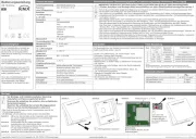
3. Öffnen des Reglers
Knopf (1) mit Schraubendreher abhebeln – Schraube (2) lösen – Gehäusedeckel (3) abziehen – Schalter-
rahmen (4) abnehmen.
3. Opening of the controller
Use a screwdriver in order to lever the knob (1) off. Loosen the screw (2). Remove the housing cover (3)
by pulling it off: Take the switch frame (4) off.
4. Installation des Reglers
Elektrischer Anschluss gemäß „Anschluss-Schaltbild“ (Bild 1) mit Schraubklemmen – Massivleiter Quer-
schnitt lastabhängig 1,5 … 2,5 mm2, Fühlerleitungsquerschnitt 0,5 mm2– kein Schutzleiter – Regler (6)
mittels Tragring (5) und Schrauben in UP-Dose auf Tapete montieren.
Nach der Installation muss der Regler mittels Poti (Bild 2) an die angeschlossene Last angepasst werden
(vgl. Punkt 14. „Lasteinstellung“).
4. Installation of the controller
The electrical connection is to be realised in accordance with the enclosed wiring diagram (picture 1) by
means of terminal screws. The cross-section of the solid conductor to be used depends on the actual load
and ranges thus from 1.5 to 2.5 mm2. The cross-section of the sensor line is 0.5 mm2. No protective earthing
wire is used. Using the supporting ring (5) and the screws enables to install the controller (6) into the UP
box. After completion of the installation works, the potentiometer provided for this purpose (picture 2) must
be used in order to adjust the controller to the actually connected load (see section 14., “Load adjustment”).
5. Installation des Überwachungsfühlers
Innerhalb der Wand und des Estrichs im Schutzrohr; – zwischen die Heizschleifen ohne Berührung; –
Parallelverlegung mit Netzkabel unzulässig; – Verlängerung bis 50 m mit 0,5 mm2(flexible Leiter mit
Aderendhülsen); ,bei Falschanschluss oder im Fehlerfall kann Netzspannung am Fühler anliegen
deshalb ist doppelte Isolierung gemäß EN 60730-2-1 vorgeschrieben!
5. Installation of the temperature monitoring sensor
The sensor line has to be laid inside a protective tube within the wall or in the floor pavement. The installa-
tion of the sensor has to be made between the serpentine heating tubes in a contactless manner. The
parallel laying with power cables is inadmissible. The sensor line can be extended up to a length of 50 m
(flexible wires with wire-end sleeves, minimum diameter 0.5 mm2). Caution: If not properly connected or
if a failure occurs, mains voltage can be present at the sensor!This is why the sensor and the wire re-
quired for the extension of the sensor line must both be double insulated, EN 60730-2-1 compliant types!
6. Gerät schließen 6. Connection of the device
For the closing of the controller, follow the steps explained in above section 3. in inverse order.
8. Funktion Nachtabsenkung
Wird an die Anschlussklemme L angeschlossen, ist die Nachtabsenkung aktiv. Dies kann z.B. über
eine externe Schaltuhr oder einen Uhrenregler realisiert werden. Die grüne Lampe zeigt die aktive Nacht-
absenkung an. (Achtung! Zweite Einspeisung) – bei Arbeiten am Regler ist auch die Nachtabsen-
kung abzuschalten!
D GB
1
2
3
4
5
6
1
2
3
4
5
6
7
8
9
7
8
9
8. Night temperature decrease function
Once L is connected to the terminal , the night temperature decrease function is rendered active. This
can, for example, be realised by an external switch clock or a clock controller. The green lamp indicates
the active state of the night temperature decrease function . Prior to(Caution: second incoming supply!)
performing any works on the controller, the night temperature decrease function too must be cut off!
9.Technische Daten
Betriebsspannung: 230V / 50Hz
Regelbereich: 5 … 30°C (Skala … 6)
Bodentemp.begrenzung 20 … 60°C (Skala 2 … 6) (intern einstellbar)
Schaltdifferenz: ca.1K
Leistungsaufnahme: ca.1W
Nachtabsenkung: ca. 4K fest; Anschluss an L
Kontakt: Schließer max. 230V 10 (1,5)A
Interner Fühler: 47k , NTC⏲
Externer Fühler (doppelt isoliert):
2k , NTC entspr. DIN EN 44574-3, DIN EN 50350 entspr. DIN EN 60730-2-1⏲
Fühlerbrucherkennung: Heizung wird abgeschaltet
Anzeigen: LED für Heizen, Nachtabsenkung
Schraubanschlüsse: 0,5 … 2,5mm2
Befestigung: in UP-Dose Ø 55 mm
Schutzart: IP30
Schutzklasse: II nach entspr. Montage
Umgebungstemperatur: 0 … 40°C
Lagertemperatur: 20 … +70°C
Funkentstörung: gemäß EN 50081-1, EN 50082-1
Operating voltage: 230V / 50Hz
Control range: 5 … 30°C (scale range … 6)
Floor temperature limitation: 20 … 60°C (scale range 2 … 6) (internally adjustable)
Switching difference: approx.1K
Power consumption: approx.1W
Night temperature decrease: approx. 4K (fixed); connection of to L
Contact: make contact, max. 230V 10(1.5)A
Internal sensor: 47k , NTC⏲
External sensor (double-insulated): 2k , NTC acc. to. DIN EN 44574-3,⏲
DIN EN 50350 in compliance with DIN EN 60730-2
Sensor breakdown detection: heating is turned off
Indicators: LED’s for heating and night temp. decrease mode
Terminal screws: screw terminals (0.5 … 2.5 mm 2)
Mounting: in an UP box (Ø 55 mm)
Degree of protection: IP30
Protection class: II (after according installation)
Ambient temperature: 0 … 40°C
Storage temperature: -20 … +70°C
Radio interference suppression: acc. to EN 50081-1 and EN 50082-1
9. Technical Data
Das Schließen des Gerätes erfolgt in umgekehrter Reihenfolge zum Öffnen.
7. Begrenzung des Einstellbereiches
Stift (7) abziehen; – Anschlag rot (8) für Maximalteperatur und Anschlag blau (9) für Minimaltemperatur
verdrehen; – Stift (7) zum Verriegeln der Anschläge wieder einstecken.
7. Limitation of the setting range
Remove the pin (7). Set the red end stop (8) for maximum and the blue one (9) for minimum temperature.
Plug-in the pin (7) to lock the end stops.