INSTALLATION
RCI 9320 / 9322
EASY READ-PROX READER
© 2022 dormakaba Canada Inc
www.dormakaba.us • Phone: 1.800.265.6630 • Fax: 1.800.482.9795 • E-mail: sales_RCI@dormakaba.com
IS9320/22
PCN2210
R10-22GR
®
Where to install proximity readers
Low to high traffic doors
Interior or exterior doors
Narrow door frames
Inside walls
Architecturally sensitive installations
A black cover is provided with the proximity reader.
A gray Slimline cover is available as 9320/21CAPG.
A white Micro cover is available as 9322/23CAPW.
Where NOT to install proximity readers
Behind metal – RF will not penetrate
On a ferrous metal surface – diminishes read range
Near TVs or monitors – RF will interfere with reader
Note: READER IS WEATHER RESISTANT. , as Do not apply sealant or gaskets to the rear of the reader
this may cause condensation to build up and adversely affect reader operation.
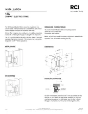
RCI 9320 Slimline Reader
1. Select appropriate space on wall for reader installation. Ensure
that there are no hidden electrical hazards prior to drilling.
2. Drill hole for reader wiring to pass through.
3. Remove changeable cover from reader if necessary. Cover is
removed by prying off from the bottom of cover only.
4. Pass the readers 6 wires through hole.
5. Hold reader against wall with LED’s at bottom, mark position of
three mounting holes.
6. Drill the three mounting holes as appropriate for the type of
fasteners being used.
7. Install / level the reader and secure with three mounting screws.
8. Install removable cover by engaging top tab and pivoting cover
down over reader. Cover should snap in place when installed
properly.
9. Cover is secured with single screw (provided) on lower edge of
cover. Cover screw must be longer than 1/4” or Important: not
internal damage will result, voiding warranty.
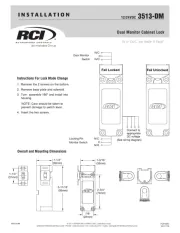
RCI 9322 Micro Reader
1. Select appropriate space on wall for reader installation. Ensure
that there are no hidden electrical hazards prior to drilling.
2. Holding reader back plate against wall, mark position for two
screw holes and center hole for reader.
3. Drill center hole 13/16” (7/8” max) in diameter. If wall is not
hollow, ensure depth of the hole is at least 2-3/4” deep to
prevent damaging reader/wiring.
4. Drill two smaller mounting holes as appropriate for type of
fastener being used.
5. If necessary, drill hole through wall for wiring to pass through.
6. Screw back plate onto reader until flush with front of reader.
7. Pass reader wires through hole and out other side as
appropriate.
8. Insert reader into hole being careful not to damage wiring.
Secure back plate with two screws provided.
9. Snap the appropriate colored cap over the back plate by
engaging one side and press the other side until it snaps
securely in place.
Mounting Instructions
Fig. 1 Fig. 2