Dormakaba DE9000 Manual


Læs gratis den danske manual til Dormakaba DE9000 (11 sider) i kategorien Ikke kategoriseret. Denne vejledning er vurderet som hjælpsom af 38 personer og har en gennemsnitlig bedømmelse på 3.5 stjerner ud af 19.5 anmeldelser. Har du et spørgsmål om Dormakaba DE9000, eller vil du spørge andre brugere om produktet?

Side 1/11
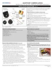
DE9300 DE9500 DE9100
INSTALLATION INSTRUCTIONS
RIM MORTISE CONCEALED VERTICAL ROD
WIRE PIG TAIL
End Cap
DE5300 DE5500 DE5100
SIZE A: (DE9000 Series)
Will fit 48" (1219 mm) door opening without cutting.
Can be cut to fit a 40 1/2" (1029 mm) minimum door opening.
SIZE B: (DE9000 Series)
Will fit 36" (914 mm) door opening without cutting.
Can be cut to fit a 34 1/2" (876 mm) minimum door opening.
End Cap Bracket
Filler (DE9000/DE5000)
REQUIRES DORMA ES-100 or AD100 POWER SUPPLY.
Easily accessible slide in and out electronics.
Meets UL, ANSI/BHMA & CBC requirements.
Note: Refer to Individual Series Installation Instructions for templating and installation of device; @ www.dorma-usa.com
These are additional instructions for installation and operation of the "Delayed Egress" unit.
NOTE: "Always disconnect power prior to making
any connections or service!"
Observe proper static discharge grounding procedures
when installing or servicing the Delayed Egress device.
SIZE AA: (DE5000 Series w/ #443 strike)
Will fit 48" (1219 mm) door opening without cutting.
Can be cut to fit a 38 3/4" (984 mm) minimum door opening.
SIZE BB: (DE5000 Series w/ #443 strike)
Will fit 36" (914 mm) door opening without cutting.
Can be cut to fit a 31 3/4" (806 mm) minimum door opening.
85 Decibel Alarm - Standard
LED Status Indicator - Standard
Nuisance Alarm - Standard
Key Switch Control - Standard
Remote Authorized Egress - Standard
Remote Re-Arm - Standard
Remote Bypass - Standard
Door Position Input - Standard, DIP Switch Setting
Auto Reset or Manual Reset, DIP Switch Setting
Auto - Stanadard (Manual - in CA)
Additional Form "C" Relays For Optional Horn etc.
(Rated 1 amp @ 30 vdc)
Touchbar/Rail
Assembly
(Delayed Egress)
Connecting Plugs
NOTE:
If cutting to length is required
carefully remove filler and
electronics for cutting. Use all
grounding precautions.
Assembly
1
Mortise Cylinder
(factory supplied)
Pt. No. 90B10SC118
Specifications
DE5000 & DE9000 SERIES
DELAYED EGRESS EXIT DEVICE
IDE - 12 8/09
1135-88 95011817
2
2
2
22
Cylinder Specification
5/16" - 11/32"
Standard 1 1/8" mortise cylinder, randomly
keyed supplied by factory. Spacer required
for longer cylinder such as when using an
IC core.
1 1/8" Standard
21/32"
DIP Switch Setting
DE Filler
Cylinder
90B10SC118
Actuator-DE
95055525
Cylinder Nut
4000-167-501
Underside of Filler
To Change Cylinder: Carefully remove filler from rail. Unscrew cylinder
nut, remove actuator and replace cylinder. Spacer required for cylinders
over 1 1/8". Insert cylinder as shown, re-install actuator & secure with
cylinder nut. Do not over tighten. Re-install filler in rail and reconnect the
small pigtail connectors. Use caution not to pinch or bind wires.
Note: DIP If switch settings required to be changed, do it now prior to
re-installing filler in rail. (See Section below.)
Underside of Filler
ON
OFF
1 2 3 4
(1) DPS: (OFF) ACTIVE (ON) NOT ACTIVE
(2) POWER UP STATE: (OFF) LOCKED (ON) UN-LOCKED
(3) NUISANCE TIME: (OFF) 1 SEC. (ON) 3 SEC.
(4) AUTHORIZED EGRESS TIME: (OFF) 10 SEC. (ON) 20 SEC.
DIP switch settings should be completed at time of initial installation;
check local building code. Factory settings are as follows:
1 - ON - NOT ACTIVE
2 - OFF - LOCKED
3 - ON - 3 SECONDS
4 - OFF - 10 SECONDS
(6310D)
CAM


Produkt Specifikationer

Mærke: Dormakaba
Kategori: Ikke kategoriseret
Model: DE9000

Har du brug for hjælp?

Hvis du har brug for hjælp til Dormakaba DE9000 stil et spørgsmål nedenfor, og andre brugere vil svare dig