(P/N) 709.058 Rev H
08/18 • © copyright 2008-2018 1
Read guide completely before beginning installation.
SAFEGUARDS FOR MOUNTING
1. Complete all welds to the safe prior to installation of the lock.
2. Keep metal dust, filings, etc. away from the lock.
3. Never oil, grease, lubricate or paint the lock.
4. If applicable, keep cables away from sharp edges and moving parts.
5. If applicable, never carry the lock by the cable.
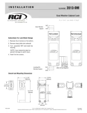
Group 2M Mechanical Lock (3390 Series)
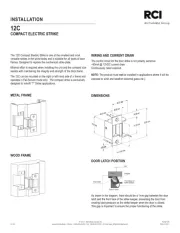
Hardware Pack, US (P/N 704004) Includes
2. Spline Key (P/N 1712)
3. Mounting Screws (P/N 2930 - Qty. 2)
4. Mounting Screw (P/N 1819)
5. Change Key (P/N 1307)
6. Insert Cover (P/N 705002)
Hardware Pack, Metric (P/N 704003) Includes
2. Spline Key (P/N 1712)
3. Mounting Screws (P/N 705006 - Qty. 2)
4. Mounting Screw (P/N 205014)
5. Change Key (P/N 1307)
6. Insert Cover (P/N 705002)
DESIGN PARAMETERS FOR MECHANICAL COMBINATION LOCKS
1. Bolt dimensions (nominal): .312 inches x 1.000 inches/8 x 25.4mm
2. Bolt movement (nominal): .465 inches/11.8mm
3. Bolt extension: .465 inches/11.8mm
4. Maximum load movable by the bolt: 5 lbs. (22N)
NOTE: LA GARD dead bolt locks may not open if more than 5 lbs. (22N) of force is
applied to the end or side of the bolt.
5. Maximum load against bolt when thrown (all directions): 224.8 lbs. (1kN)
6. The lock can be fitted to safes or vault doors of any material.
NOTE: As is the case with all mechanical and electronic locking devices, the container and boltworks must be designed to
protect the lock from all possible attack methods and angles, including front side, side walls, and back side of the lock.
Prepare for New Installation of the Lock (If Required)
1. Use the template provided to establish the exact locations (relative to the spindle hole)
of the mounting holes for the lock assembly.
2. The spindle hole diameter can be a minimum of .406” (10.3mm) to a maximum of .438”
(11.1mm). The .406” (10.3mm) diameter is recommended. Spindle hole must be
deburred.
3. The dial assembly mounting screws require drilled and tapped holes to 3/8” (9.5mm)
depth if possible (minimum 1/4” or 6.4mm depth required.) Drill either the two
horizontal mounting holes or the two vertical holes.
4. When mounting the lock unit (i.e., integrating it in a boltwork), make sure that the lock
bolt has clearance to freely move to its end positions and that the shifting force works
only in the axial direction (direction of movement). Lateral forces should not be exerted
on the lock.
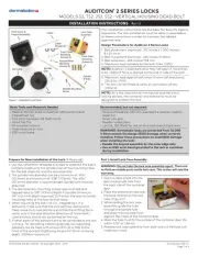
INSTALLATION INSTRUCTIONS
Figure 2
DOOR
Total Mounting Thickness
(plus .875")
Optional hardplate
or mounting bracket
Figure 3
1
5
6
2
4
3
Figure 1
MECHANICAL
3390 SERIES GROUP 2M LOCK