Drayton Digistat 22902 Manual

Drayton Termostat Digistat 22902

Læs gratis den danske manual til Drayton Digistat 22902 (4 sider) i kategorien Termostat. Denne vejledning er vurderet som hjælpsom af 19 personer og har en gennemsnitlig bedømmelse på 4.7 stjerner ud af 10 anmeldelser. Har du et spørgsmål om Drayton Digistat 22902, eller vil du spørge andre brugere om produktet?

Side 1/4
Programmable 2-Channel
Room Thermostat
Model: 22902
Technical Helpline Tel: 0333 6000 622
Website: www.draytoncontrols.co.uk
Email: customer.care@draytoncontrols.co.uk
User and Installation Guide 06490346001 Iss B
User and Installation Guide 06490346001 Iss BUser and Installation Guide 06490346001 Iss B
Installation guide
Before Installation
Before Installation
Before Installation
Before InstallationBefore Installation
If you do not have the knowledge to install the thermostat
safely then you must arrange for a competent electrician
to install it for you. Wiring must conform to the current IEE
regulations.
Prior to commencing the installation you must ensure the
mains supply is switched off.
1.
1.
1.
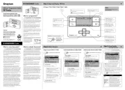
1.1. Remove the front cover by releasing the 2 screws at the
bottom. Mounting holes and electrical connections are found
underneath the hinged black cover (Fig 1).
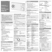
3a. Complete the wiring according to the connections
shown in Fig 3.
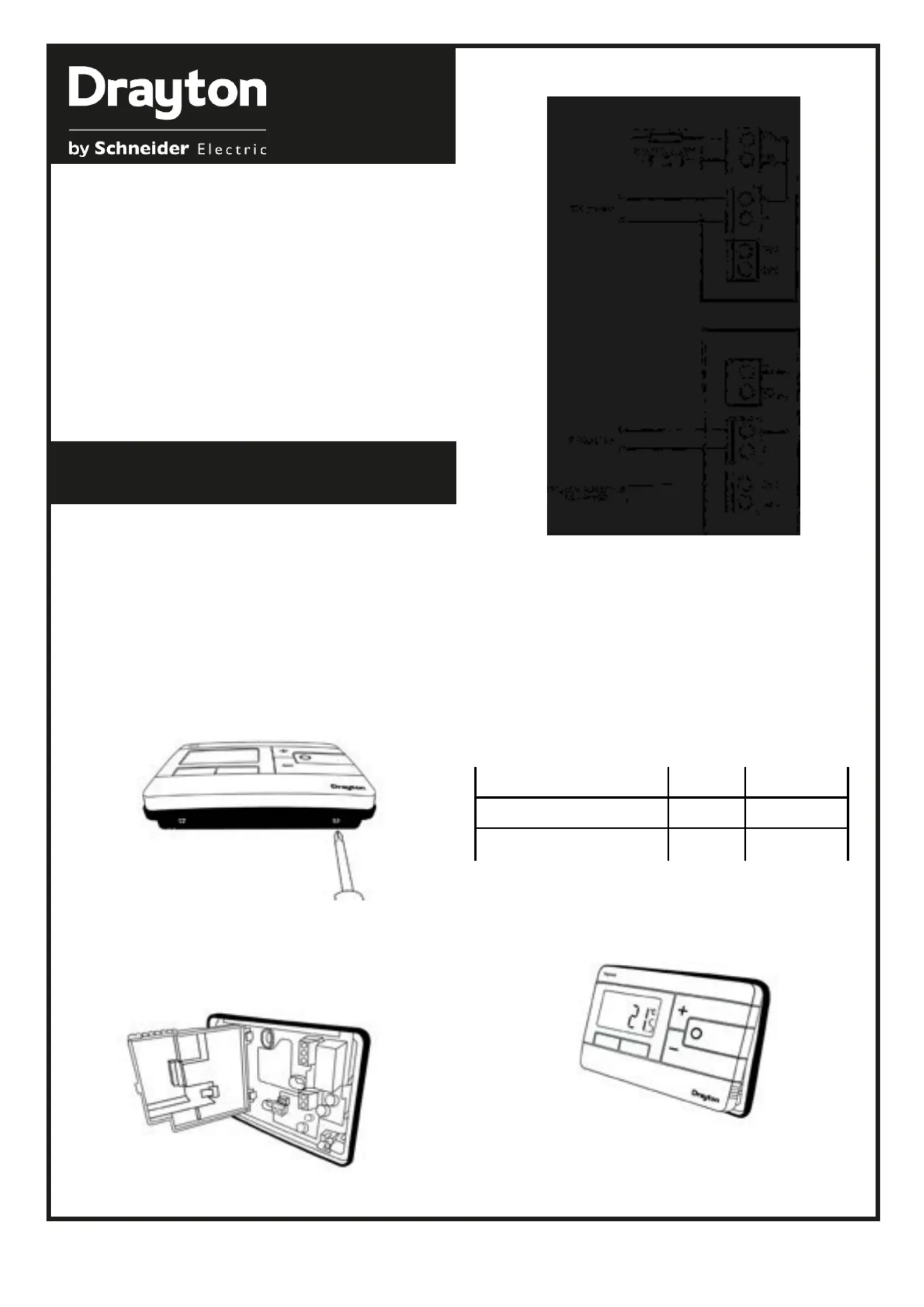
4. Close the black hinged terminal cover and replace the
front cover by locating the two latches at the top then fasten
the 2 screws at the bottom (Fig 4).
(Fig. 4)
5. The Digistat is now installed and will automatically start to
control the room temperature.
10 Upper CH water set point 30-80°C Default 70°C
11 Lower CH water set point 10-25°C Default 10°C
12 Set HW temp 45-65°C Default 60°C
Digistat
3rd Generation
(Fig. 1)
2.
2.
2.
2.2. Fix back plate directly onto the wall using suitable wall plugs
and screws or mount over existing wall box (Fig 2).
(Fig. 2)
(Fig. 3)
3b. If your boiler supports OpenTherm please follow these
3b. If your boiler supports OpenTherm please follow these 3b. If your boiler supports OpenTherm please follow these
instructions:
instructions:
instructions:
instructions:instructions:
Remove the OpenTherm cables from the existing controller
or thermostat. Connect the cables to the OpenTherm termi-
nals OT1 and OT2 on the Digistat. Polarity is not important.
Wire L and N from a separate supply with a 3A fuse.
Note that when connected to an OpenTherm boiler, Installer
Options 06 Valve Protection and 08 Application Type are not
available. The following options will appear in the Installer
Options list:
To make changes to the default Installer Options shown
below, enter the Installer Options menu by pressing the
settings button for 3 seconds. This allows access to the
User Menu 01, the Advanced User Settings Menu 02, the
Installer Settings 03, and Service Interval Settings 04. Use the
+ and - buttons to scroll to Installer Options and press O to
select. You can exit the menu by pressing until you have
returned to the home screen. In the Installer Options menu
(Fig 8), scroll through the options using the + and - buttons
and press O to select. Scroll through the different settings
using the + and - buttons and press O to select and save. (Fig
9 shows Option 02 OFF).
(Option 01) Partial Sight Assistant
(Option 01) Partial Sight Assistant(Option 01) Partial Sight Assistant
When enabled, audible tones indicate when the setpoint is
more than, less than or equal to the current room temper-
ature when a user manually adjusts the setpoint using the +
button: Setpoint > room temperature - single high tone per
0.5°C increase
Setpoint = room temperature - double tone
Setpoint < room temperature - single low tone per 0.5°C
decrease
(Option 02) Frost Protection
(Option 02) Frost Protection (Option 02) Frost Protection
The Digistat will switch on the heating if the temperature
falls to 5°C and maintains a temperature of 7°C even when in
OFF mode.
(Option 03) Minimum Setpoint Limit
(Option 03) Minimum Setpoint Limit (Option 03) Minimum Setpoint Limit
Change minimum setpoint temperature. After any changes to
setpoint limits, all setpoints in AUTO, MANUAL, BOOST and
HOLIDAY modes will be modified to conform accordingly.
(Option 04) Maximum Setpoint Limit
(Option 04) Maximum Setpoint Limit (Option 04) Maximum Setpoint Limit
Change maximum setpoint temperature. After any changes to
setpoint limits, all setpoints in AUTO, MANUAL, BOOST and
HOLIDAY modes will be modified to conform accordingly.
(Option 05) Optimum Start
(Option 05) Optimum Start (Option 05) Optimum Start
When enabled, this uses current ambient temperature, the
next scheduled setpoint and heat gain data captured by the
device to adjust the thermostat setpoint early, so the ambient
temperature is at the required level when the next event
starts.
Delayed Start
Delayed Start
Delayed Start
Delayed Start Delayed Start
When enabled, this uses current ambient temperature, cur-
rent event setpoint and heating characteristics environ-of the
ment to delay implementation of the setpoint if the ambient
temperature is already close to it, therefore saving energy.
(Option 06) Valve Protection Time
(Option 06) Valve Protection Time (Option 06) Valve Protection Time
In some hydronic heating systems it may be required to pro-
tect the valve by operating it for a given time. When enabled,
this maintenance feature ensures that each relay output is
operated for at least one (1) minute each week.
(Option 07) Sensor Fault Function
(Option 07) Sensor Fault Function (Option 07) Sensor Fault Function
In the event of a sensor fault, central heating output is re-
duced to 30% by turning heating ON for 3 minutes, then OFF
for 7 minutes.
(Option 08) Application Type
(Option 08) Application Type(Option 08) Application Type
Select the central heating system energy type.
(Option 09) System Capability
(Option 09) System Capability (Option 09) System Capability
Select the flow capability of the heating system.
(Option 13) Installer Settings Lock
(Option 13) Installer Settings Lock (Option 13) Installer Settings Lock
When enabled, you can lock the installer settings until a 3
digit code is entered.
(Option 20) Reset
(Option 20) Reset
(Option 20) Reset
(Option 20) Reset(Option 20) Reset (Service Interval settings are NOT reset)
Reset the Digistat to its original factory settings.
Service Interval Options continued on reverse.
INSTALLER OPTIONS
(Fig. 8) (Fig. 9)
What is it Select etween b Default
Installer ptions O
01 OFF ON
02
Partial Sight Assistant
Frost Protection ON OFF ON
03 5 High mit Li 5
04 Low imit L 30 30
05
Low Set Point C
High Set Point C
Optimum Start OFF Delayed tart S Optimum tart S OFF
06 OFF 5 4 3 2 1 OFF
07 OFF ON OFF
08 Gas Electric Oil Heat Pump Gas
09 Fast low F Normal/Slow Flow Fast low F
13 OFF ON OFF
20
Valve ection ime Prot T
(Mins) Sensor ault unction F F
Application ype T
System apability C
Installer ettings S
Lock Reset NO YES NO
Service Internal Options
01 Si Status OFF ON OFF
02 Si pe Ty Reduced omfort C Heating OFF No Effect Reduced omfort C
03 Si Due Date YY/MM/DD
04 Si arning W 0 99 30
05 Si Due Alarm OFF ON OFF
06 Si Boost OFF ON OFF
07 Si Password Reset Select -digit IN 4 P 0000
bEEP
FrSt
LoSP
HiSP
OPSt
vPrt
SEnS
APPL
SySt
LOC
rSEt
StAt
tYPE
dUE
WArn
ALAr
bSt
COdE
EXit
Screen
Screen
Screen
ScreenScreen
Abbreviations
Abbreviations
Abbreviations
AbbreviationsAbbreviations
ON


Produkt Specifikationer

Mærke: Drayton
Kategori: Termostat
Model: Digistat 22902

Har du brug for hjælp?

Hvis du har brug for hjælp til Drayton Digistat 22902 stil et spørgsmål nedenfor, og andre brugere vil svare dig


Termostat Drayton Manualer

Drayton

Drayton RTS10 Manual

5 Oktober 2024
Drayton

Drayton RTS2 Manual

16 September 2024
Drayton

Drayton PTS1 Manual

5 September 2024
Drayton

Drayton Easy 2 Manual

5 September 2024

Termostat Manualer

Nyeste Termostat Manualer