Drayton Digistat RF902 Manual

Drayton Termostat Digistat RF902

Læs gratis den danske manual til Drayton Digistat RF902 (4 sider) i kategorien Termostat. Denne vejledning er vurderet som hjælpsom af 24 personer og har en gennemsnitlig bedømmelse på 5.0 stjerner ud af 12.5 anmeldelser. Har du et spørgsmål om Drayton Digistat RF902, eller vil du spørge andre brugere om produktet?

Side 1/4
100 mm
N L 1 2 3 4
Installation Guide
Wireless 2-channel
Programmable Thermostat
Befor stallatione In
If yo du o no havt e th knowledge e t instal tho l e thermosta safely t
then you must arrange for competen elec icia a t tr n t instalo l i for t
you. Wirin mustg conform t tho e current IEE regulations.
Prior t commencin tho g e n installatio yo mustu ensure the
mains sup ly isp d switche off.
1. Installing the Digistat Receiver
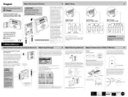
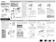
1a. Location of th receivere
Location
The Digistat Receiver should be mounted in a convenient
position, close to the bolier or central heating system
wiring centre. It is recommended that the receiver is
mounted on the wall nearest the final location and not
less than 1m from the boiler side panel.
Warning: Installing the receiver too close to metal
objects or mains cables may interfere with the radio
signal.
Digistat
3r Generationd
(Fig 1)
(Fig 3)
(Fig 2)
1b. Installation of th wallplatee
F ing (mini m wallplatix mu e clearances shown below)
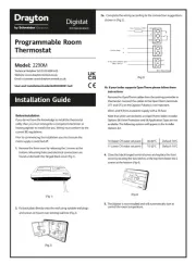
2. Wiring
i. Loose thn e securing screws remov, e e th wallplate, an if d
surface wirin ig s to e b u dse , snap out e th cable entry s iptr
on th botto edge m e of th wallplate e wit pair of pliers.h a
ii. Fix the wallplate, ter nal ami s t the top, either direc ontt o the
3. Replace the front cover of the receiver by locating the two latches
at the top and then fasten the two screws at the bottom. As
soon as the receiver has power it willDigistat be ready for
pairing with the Digistat RF Thermostat .
This product is double insulated s and doe not re requi an earth
conn ction. The receiver sh uld bee o wired to the combi boiler or
central heating wiring using the correct type of cable or flex.
The receiver sh uldo be wired in to replace hard-wired room
or programmable thermostats shown on the system or boiler
wiring diagrams. Always ch eck other manufacturers’
instructions for compati il ty.b i
Relay Outp ut
Model: RF902
Consists of a Thermostat RF90T nd Receiver RF90D
Technical Helpline Tel: 0333 6000 622
Website: www.draytoncontrols.co.uk
Email: customer.care@draytoncontrols.co.uk
Userand Installation Guide06490311001 Iss E
BOILER
Preferred side of boiler
The range may be affected by composition/density
and number walls between the Digistat
of
thermostat and receiver
Radio Signal Range:
30m Typically
REC
INSTA ER OPTIONSLL
To make changes to the default Installer Options shown below,
enter the Installer Options menu by pressing the settings
button for 3 seconds. This al lows access to the User Menu
01, the Advanced User Settings Menu 02, the Installer Settings
03, and Service Interval Settings 04. Use the + and - buttons to
scroll to Installer Options and O press to select. You can exit the
menu by pressing until you have d returne to the home
screen. In the Installer Options menu (Fig 7), sc ollr thro ghu the
options using the + and - buttons and O press to select. Scroll
thro ghu the different settings using the + and - buttons and
press O to select and save. (Fig shows 8 Option 02 OFF).
Note: S d c l can be econ hanne
u d f or hot w r or se ate se ondc
he ing c lat hanne
(Option 01) Partial Sight Assistant (beep)
When enabled, aud ble to esi n indi atec when the setpoint is
more than, less than or equal to the current room temperature
when a user manually adjusts the t setpoin using the + button:
Setpoint > room temperature - sin leg high e ton per 0.5°C
increase
Setpo t in = room temperature - double to e n
Setpoint < room temperature - sin leg low tone per 0.5°C
decrease
(Option 02) Frost Protection
The will switchDigistat on the heating if the temperature falls
to 5°C and mai tainsn a temperature of 7°C even when
in OFF mode.
(Option 03) Minimum Setpoint Limit
Change minimum setpoint temperature. After any changes to
setpoi limits,nt all setpoi tsn in AUTO, MANUAL, BOOST and
HOLIDAY modes will be modified to conform accordingly.
(Option 04) Maximum Setpoint Limit
Change maximum setpoint temperature. After any changes to
setpoi limits,nt all setpoi tsn in AUTO, MANUAL, BOOST and
HOLIDAY modes will be modified to conform accordingly.
(Option 05) Optimum Start
When enabled, this uses current amb ent temperature, the next i
sch duled setpo t ande in heat gain data cap uredt by the device to
adjust the thermostat t setpoin early, so the amb ent i
temperature is at the re red level when the next event starts.qui
Delayed Start
When enabled, this uses current amb ent temperature,i current
event setpo t andin heating characteris icst of the environment
to delay implementation of the setpo int if the amb ent i
temperature is already close to it, therefore saving energy.
(Option 06) Valve Protection Time
In some hy ronicd heating systems it may be re redqui to pr tect o
the valve by operating it for a given time. When enabled, this
mai tenancen feature ensures that each t relay o tpu u is operated
for at least e on (1) minute each week.
(Fig 7) (Fig 8
control room temperatures and hot water times.
(Fig 5)
6. The Digistat is now installed and will automaticly start to
(Fig 6)
4. Pairing guide for the RF902
1. Press and hold cog 3s button until you see USEr 01.
2. Press the plus button twice until you see InSt 03 an
press O button to select.
3. You will now see bEEP 01, press minus twice to rSEt 20
and press the O button to select.
4. no will be flashing, press plus button to see YEs is
flashing
DON'T PRESS ANYTHING ELSE
(Go to receiver)
5. Press and hold the left button until the lights flash
orange and green, then release.
(Go back to digistat)
6. Press the O selected button once to liven up screen and
align to select YEs.
7. SCAn will be displayed.
8. After a few seconds you will see a big CH appear on the
screen.
9. Press the plus button so you see dHW and CH, press O
and you will see PAIr rEC.
All lights will go off on the receiver.
10.To test this has worked, press the plus button on your
digistat to call for heat,
A green light will be visible on the receiver to indicate
the call for heat this means it's all working.
(Fig 4
5. Two heating Zones
1. Pair the First Digistat up to step 8 from above.
2. Press the O button to see the big CH on the Digistat, just
press O. Do not press + to see dHW.
3. It will display SCAn, then PAIr rEc and your first Digistat
will be controlled on the right channel on the receiver.
4. Pair the second Digistat up to step 7 from above.
5. PAIr rEc will be displayed and your second Digistat will
be paired to the left channel on the receiver.


Produkt Specifikationer

Mærke: Drayton
Kategori: Termostat
Model: Digistat RF902

Har du brug for hjælp?

Hvis du har brug for hjælp til Drayton Digistat RF902 stil et spørgsmål nedenfor, og andre brugere vil svare dig