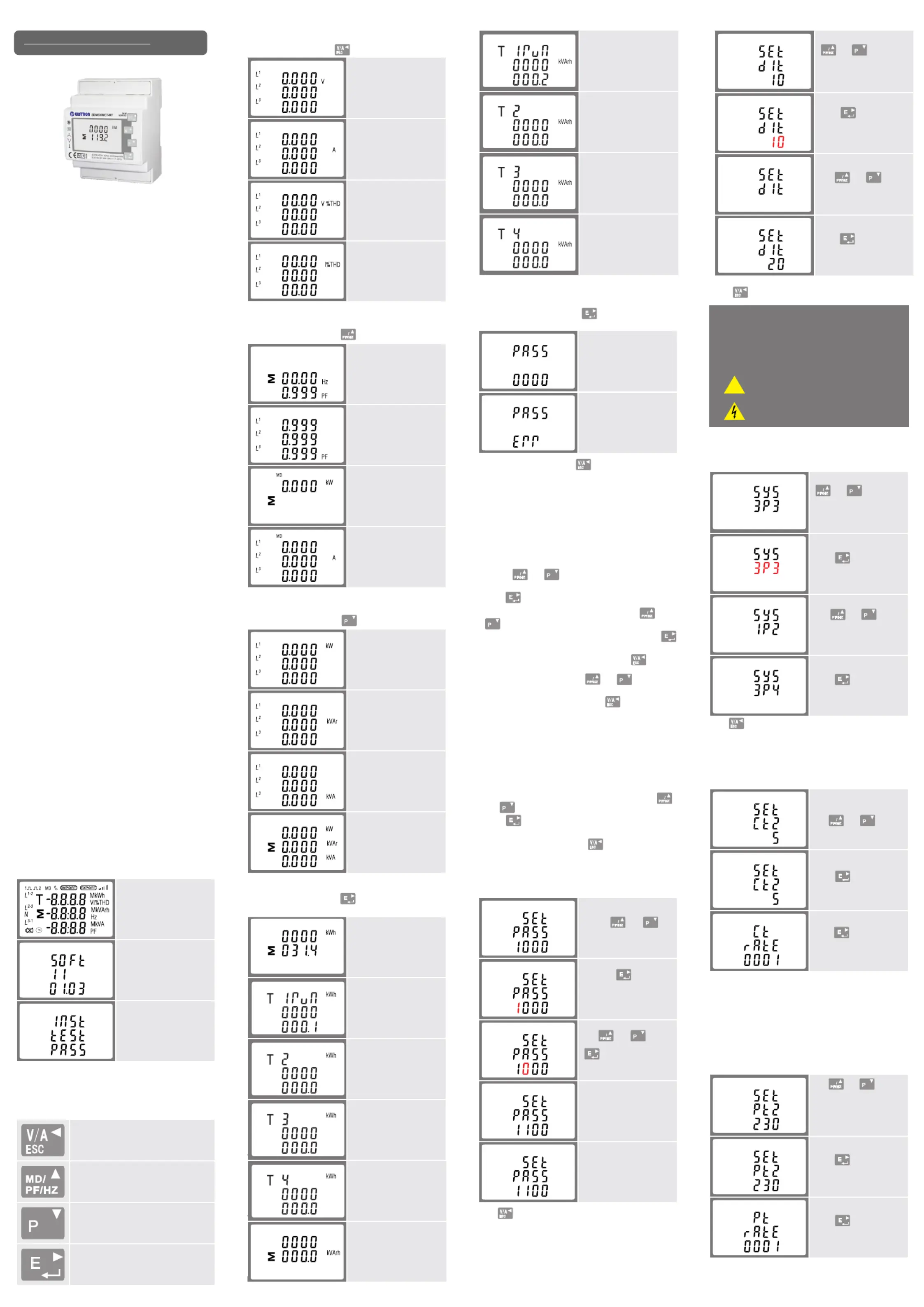
Eastron SDM630MCT-MT Manual

Eastron Måling SDM630MCT-MT

Læs gratis den danske manual til Eastron SDM630MCT-MT (2 sider) i kategorien Måling. Denne vejledning er vurderet som hjælpsom af 24 personer og har en gennemsnitlig bedømmelse på 4.8 stjerner ud af 12.5 anmeldelser. Har du et spørgsmål om Eastron SDM630MCT-MT, eller vil du spørge andre brugere om produktet?

Side 1/2
1.Introduction
This document provides operating, maintenance and
installation instructions. This unit measures and displays
the characteristics of single phase two wires(1p2w),three
phase three wires(3p3w) and three phase four wires(3p4w)
networks.The measuring parameters include voltage(V),
frequency(Hz),current(A),power(kW/Kva/Kvar), mport, i
export and total Energy(kWh/kvArh).The unit can also
measures Maximum demand current and power. his is T
This unit is a 1A or 5A current transformer operated and can
be configured to work with a wide range of CTs. Built-in pulse
and Modbus or M Bus outputs.Configuration is password -
protected.
This unit can be powered from a separate auxiliary (AC or DC)
supply. Alternatively it can be powered from the monitored
supply by linking the voltage reference and neutral reference in
to terminals 5 and 6 (Please refer to wiring diagram).
1.1 Unit Characteristics
The unit can measure and display:
• Voltage and THD% (total harmonic distortion) of all phases
• Line frequency
• Currents,current demand and current THD% of all phases
• Power, maximum power demand and power factor
Active energy import d and exportede
• Reactive energy imported and exported
1.2 Current Transformer Primary Current
1.3 RS485 Modbus RTU
1.4 Pulse output
Two pulse outputs that pulse measured active and reactive
energy.The Pulse 2 constant for active energy is 3200imp/kWh.
(Terminals 11 & 12) The pulse width for Pulse 1 can be set
from the set-up menu (Terminals 9 & 10).
2.Start Up Screens
The first screen lights up
all display segments and
can be used as a display
check.
S ftw re version information o a
The interface performs a
self-test and indicates the
result if the test passes.
*After a short delay, the screen will display active energy
measurements.
3.Measurements
The buttons operate as follows:
Selects the Voltage and Current display
screens. In Set-up Mode, this is the “Left”
or “Back” button.
Select the Frequency and Power factor
display screens. In Set-up Mode, this is
the “Up” button.
Select the Power display screens. In Set-
up Mode, this is the “Down” button.
Select the Energy display screens. In Set-
up mode, this is the “Enter” or “Right”
button.
3.1 Voltage and Current
Each successive press of the button selects a new parameter:
Phase to neutral voltages.
Current on each phase.
Phase to neutral voltage
THD%.
Current THD% for each
phase.
3.2 Frequency and Power Factor and Demand
Each successive press of the button selects a new range:
Frequency and Power
Factor (total).
Power Factor of each
phase.
Maximum Power Demand.
Maximum Current
Demand.
3.3 Power
Each successive press of the
button selects a new range:
Instantaneous Active
Power in kW.
Instantaneous Reactive
Power in kVAr.
Instantaneous Volt-Amps
in KVA.
Total kW, kVArh, kVA.
3.4 Energy Measurements
Each successive press of the button selects a new range:
Total active energy in kWh.
Total reactive energy in
kVArh.
4.Set Up
To enter set-up mode, press the
button for 3 seconds,
until the password screen appears.
Setting up is password-
protected so you must
enter the correct password
(default ‘1000’) before
processing.
If an incorrect password
is entered, the display will
show:
PASS Err
To exit setting-up mode, press
repeatedly until the
measurement screen is restored.
4.1 Set-up Entry Methods
Some menu items, such as password and CT, require a
four-digit number entry while others, such as supply system,
require selection from a number of menu options.
4.1.1 Menu Option Selection
and buttons to scroll through the
different options of the set up menu.
2. Press
to confirm your selection
3. If an item flashes, then it can be adjusted by the
and
buttons.
4. Having selected an option from the current layer, press
to confirm your selection. The SET indicator will appear.
5. Having completed a parameter setting, press
to return
to a higher menu level. The SET indicator will be removed
and you will be able to use the
and buttons for
further menu selection.
6. On completion of all setting-up, press
repeatedly until
the measurement screen is restored.
4.1.2 Number Entry Procedure
When Setting up the unit, some screens require the entering
of a number. In particular, on entry to the setting up section, a
password must be entered. Digits are set individually, from left
to right. The procedure is as follows:
1. The current digit to be set flashes and is set using the
and
buttons.
2. Press
to confirm each digit setting. The SET indicator
appears after the last digit has been set.
3. After setting the last digit, press
to exit the number
setting routine. The SET indicator will be removed.
4.2 Change Password
Use the and
to choose the change
password option.
Press the to enter the
change password routine.
The new password screen
will appear with the first
digit flashing.
Use and to set
the first digit and press
to confirm your
selection. The next digit
will flash.
Repeat the procedure for
the remaining three digits.
After setting the last digit,
SET will show.
Press
to exit the number setting routine and return to the
Set-up menu. SET will be removed.
4.3 DIT Demand Integration Time
This sets the period in minutes over which the current
and power readings are integrated for maximum demand
measurement. The options are: off, 5, 10,15 30,60 minutes.
From the set-up menu, use
and buttons
to select the DIT option.
The screen will show
the currently selected
integration time.
Press to enter the
selection routine. The
current time interval will
flash.
Use and
buttons to select the time
required.
Press to confirm the
selection. SET indicator
will appear.
Press to exit the DIT selection routine and return to the menu.
4.4 Supply System
Use this section to set the type of electrical system.
From the set-up menu, use
and buttons to
select the system option.
The screen will show the
currently selected power
supply.
Press to enter the
selection routine. The
current selection will flash.
Use and
buttons to select the
required system option:
1P2(W),3P3(W) ,3P4(W).
Press to confirm the
selection. SET indicator
will appear.
Press
to exit the system selection routine and return to
the menu. SET will disappear and you will be returned to the
main set-up Menu.
4.5 CT
The CT option sets the secondary current (CT2 1A or 5A)
of the current transformer (CT) that wires to the meter.
From the set-up menu,
use and buttons
to select the CT option.
Secondary CT setting
Press to enter the
CT secondary current
selection routine.:5A/1A
4.6 PT
The PT option sets the secondary voltage (PT2 100 to 500V) of
the voltage transformer (PT) that may be connected to the meter.
and buttons
to select the PT option.
The screen will show the
voltage PT secondary
voltage value. The default
value is 230V.
Secondary PT setting
Press to enter the
PT secondary voltage
selection routine. The
range is from 100 to 500V.
For example, if set the ratio to be 100,it means the primary
voltage equals secondary voltage x100.
Warnings
Important Safety Information is contained in the
Maintenance section. Familiarize yourself with this
information before attempting installation or other
procedures. Symbols used in this document:
Risk of Danger: These instructions contain
important safety information. Read them before
starting installation or servicing of the equipment.
Caution: Risk of Electric Shock
User Manual V1.1
1. Use the
The unit has a default setting of 3Phase 4wire (3P4).
MD
MD
MD
MD
MD
MD
MD
MD
MD
MD
MD
MD
MD
Three Phase Multifunction Energy Meter
Use
DIN RAIL SMART METER
FOR SINGLE AND THREE PHASE
ELECTRICAL SYSTEMS
* Please note for the MID approved version device,you will
only have one opportunity to set the ratio.
!
SDM630 MCT-MT
C1C2
C1 C2
C1 C2
C1 C2
T1 reactive energy in kVArh
T2 reactive energy in kVArh
T1 active energy in kWh
T2 active energy in kWh
SDM630MCT-MT has a RS485 port with Modbus RTU
protocol.
Rs485 provide a means of remotely monitoring and
controlling the unit. Set-up screens are provided for
settingup the communication port.
C1 C2
• Multi-tariff
SDM630MCT-MT is CT operated you will need to set the
correct CT ratio.
C1 C2
T3 active energy in kWh
C1 C2
T4 active energy in kWh
C1 C2
T3 reactive energy in kVArh
C1 C2
T4 reactive energy in kVArh
Set CT Ratio value
Press to enter the
CT Ratio setting screen.
The range is from 0001
to 2000.
For example, if using a 100/5A current transformer you
will enter 0020, as you need to divide the primary by the
secondary to get the ratio (CT rate).
Set PT ratios value
Press to enter the PT
ratio screen.
The range is from 0001
to 9999.
As an example: If using 100/5A CT, you will need to insure
CT2 (Secondary) is set to 5 and CT rate is 0020. You divide
the primary by the secondary to get the CT rate to be entered
(100/5=20).
• Changing password
• Supply system selection 1p2w, 3p3w, 3p4w
• Demand Interval time
• Reset for demand measurements
• Pulse output duration
The unit has password-protected set-up screens for:


Produkt Specifikationer

Mærke: Eastron
Kategori: Måling
Model: SDM630MCT-MT

Har du brug for hjælp?

Hvis du har brug for hjælp til Eastron SDM630MCT-MT stil et spørgsmål nedenfor, og andre brugere vil svare dig