ZTM 1
ZTM 2
9
7
2
3
6
5
8
1
10
11
4
Un
LED
T = t1 + t2
ON
t1 t2
OFF
Un
LED
OFF
T = t1 + t2
ON
t1 t2
Un
Un
T
Un
<T
Un
2
ZTM 1
ZTM 2
Multi-function time relay
Characteristic
Description
EN
• Multi-function time relay for universal use in automation, control and regulation
or in house installations.
• All functions initiated by the supply voltage, except for the asher function, can
use the control input to inhibit the delay (pause).
• Relay mode selection - according to the set function, permanently closed,
permanently open, function of memory latch with delay (ZTM 1) / switching of
the second relay according to supply voltage (ZTM 2).
• Universal supply voltage AC/DC 12 – 240 V.
• Time scale 50 ms - 30 days divided into 10 ranges: (50 ms - 0.5 s / 0.1 s - 1 s /
1 s - 10 s / 0.1 min - 1 min / 1 min - 10 min / 0.1 hr - 1 hrs / 1 hrs - 10 hrs / 0.1 days -
1 day / 1 day - 10 days / 3 days - 30 days).
• Output contact:
ZTM 1: 1x changeover / SPDT 16 A
ZTM 2: 1x changeover / SPDT 16 A, 2x changeover / DPDT 8 A
• Multifunction red LED ashes or shines depending on the operating status.
Indication of operating states
pause
ON, timing
OFF, timing
pause
FUNC. SETTINGS FUNCTION MODE
The desired function a-j is set with the FUNC rotary switch.
OFF. RELAY OPEN MODE
ON. RELAY CLOSED MODE
k. Function: MEMORY LATCH with delay
(Only for ZTM 1)
2 INST. SECOND RELAY INSTANTANEOUS
Only for ZTM 2)
When the supply voltage is applied, the relay is open. If the control contact is closed,
the relay closes and the time delay T starts. It does not matter the length of the control
pulse. When the timing is complete, the relay opens. If the control contact is closed
during timing, the relay opens immediately. Each time the control contact closes
during relay timing, it changes status.
The second relay switches according to the supply voltage.
The rst relay switches according to the function (a-j) set by the trimmer FUNC.
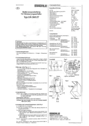
Relay mode selection
1. Control input „S“
2. Supply indication
3. Time range setting
4. Function setting
5. Output contacts 2 (25-26-28)
6. Output contacts 1 (15-16-18)
7. Supply terminals
8. Output contacts 3 (35-36-38)
9. Output indication
10. Fine time setting
11. Relay mode selection
Trigger
Warning
Device is constructed for connection in 1-phase AC/DC 12- 240 V main alternating current
voltage and must be installed according to norms valid in the state of application.
Connection according to the details in this direction. Installation, connection, setting
and servicing should be installed by quali ed electrician sta only, who has learnt
these instruction and functions of the device. This device contains protection against
overvoltage peaks and disturbancies in supply. For correct function of the protection of
this device there must be suitable protections of higher degree (A, B, C) installed in front
of them. According to standards elimination of disturbancies must be ensured. Before
installation the main switch must be in position “OFF” and the device should be de-
energized. Don´t install the device to sources of excessive electro-magnetic interference.
By correct installation ensure ideal air circulation so in case of permanent operation and
higher ambient temperature the maximal operating temperature of the device is not
exceeded. For installation and setting use screw-driver cca 2 mm. The device is fully-
electronic - installation should be carried out according to this fact. Non-problematic
function depends also on the way of transportation, storing and handling. In case of any
signs of destruction, deformation, non-function or missing part, don´t install and claim
at your seller it is possible to dismount the device after its lifetime, recycle, or store in
protective dump.
ZTM 1 ZTM 2
T
Un
T
TT
Un
T
Un
T
TT
Un
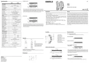
EBERLE
Klingenhofstrasse 71
90411 Nürnberg
Tel.: +49 911 5693 – 0
Fax: +49 911 5693 536
E-Mail: info@eberle.de
Web: www.eberle.de
ZTM 2ZTM 1
16
18
15
S
A2
A1
Un
+
15 16 18
A1SA2
~
+
~
-
Un
15 16 18
25 26 28
35 36 38
A1SA2
~
+
~
-
Un
Technical parameters
Power supply
Supply terminals:
Voltage range:
Power input (max.):
Supply voltage tolerance:
Supply indication:
Time circuit
Number of functions:
Time ranges:
Time setting:
Time deviation:*
Repeat accuracy:
Temperature coe cient:
Output
Number of contacts 1:
Current rating:
Breaking capacity:
Electrical life (AC1):
Number of contacts 2 (3):
Current rating:
Breaking capacity:
Electrical life (AC1):
Switching voltage:
Max. power dissipation:
Output indication:
Mechanical life:
Control
Control. terminals:
Load between S-A2:
Impulse length:
Reset time:
Other information
Operating temperature:
Storage temperature:
Dielectrical strength:
supply - output 1
supply - output 2 (3)
output 1 - output 2
output 2 - output 3
Operating position:
Mounting:
Protection degree:
Overvoltage category:
Pollution degree:
Cross-wire section – solid/
stranded with ferrule (mm
2
):
Dimensions:
Weight:
Standards:
A1 - A2
AC/DC 12 - 240 V (AC 50 - 60 Hz)
2 VA / 1.5 W 2.5 VA / 1.5 W
-15 %; +10 %
green LED
11 10
50 ms - 30 days
rotary switches and potentiometers
5 % - mechanical setting
0.2 % - set value stability
0.01 % / °C, at = 20 °C (0.01 % / °F, at = 68 °F)
1x changeover / SPDT (AgNi)
16 A / AC1
4000 VA / AC1, 384 W / DC
50 000 operations
x 2x chang. / DPDT (AgNi)
x 8 A / AC1
x 2000 VA / AC1, 192 W / DC
x 10 000 operations
250V AC / 24V DC
1.2 W 2.4 W
multifunction red LED
10 000 000 operations
A1-S
Yes
min. 25 ms / max. unlimited
max. 150 ms
-20 °C to +55 °C
-30 °C to +70 °C
4kV AC
x 1kV AC
x 1kV AC
x 1kV AC
any
DIN rail EN 60715
IP40 from front panel / IP20 terminals
III.
2
max. 1x 2.5 or 2x 1.5 /
max. 1x 2.5 (AWG 12)
90 x 17.6 x 64 mm (3.5 x 0.7 x 2.5 inch)
62 g 85 g
EN 61812-1
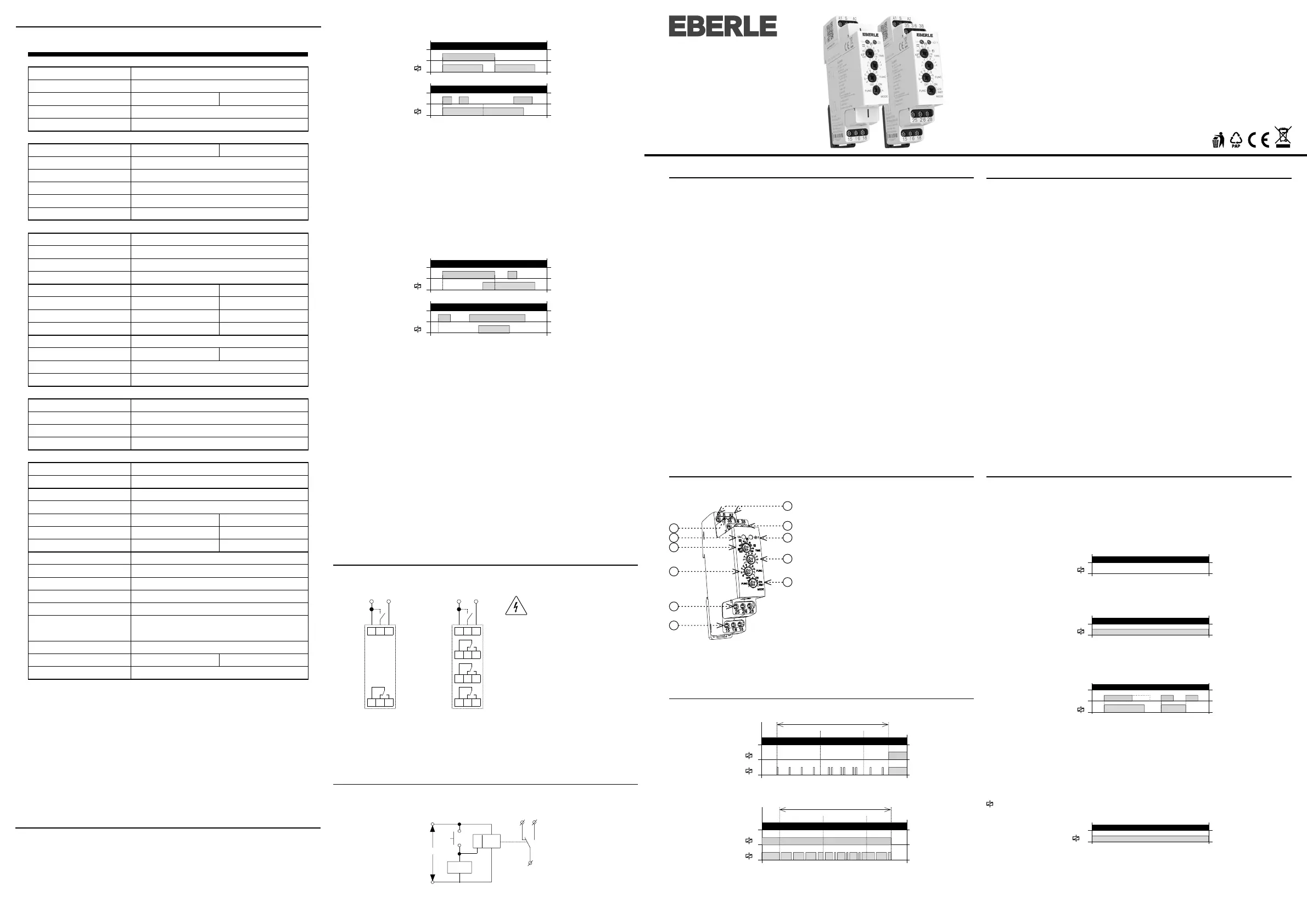
When the supply voltage is applied, the relay is open. When the control contact is
closed, the relay closes and the time delay T begins. When the control contact is
opened, the relay closes and the time delay T begins. If the control contact is open
during timing, the relay remains closed for 2T. When the timing is complete, the relay
opens. Any other change of control contact status during timing is ignored.
When the supply voltage is applied, the relay is open. If control contact is closed, time
delay T starts. When the control contact is opened, a new time delay T begins. If the
control contact is open during timing, the relay closes at the end of the timing and
opens the relay after the new time delay. Any other change of control contact status
during timing is ignored.
i. INTERVAL ON / OFF
j. ON / OFF DELAY
Trigger
Trigger
Trigger
Trigger
* for adjustable delay <100ms, a time deviation of ± 10ms applies
Connection
ZTM 2:
The potential di erence between
the supply terminals (A1-A2), output
contact 2 (25-26-28) and output
contact 3 (35-36-38) must be a
maximum of 250V AC rms / DC.
load
Possibility to connect load onto controlling input
It is possible to connect the load (e.g.: contactor) between terminals S-A2, without any
interruption of correct relay function.
Wiring diagram