No: 341247 3/19
Wattstopper
®
Toggle SSL7A Compliant 2-Wire LED Dimmer, Incandescent, Halogen: 300W, CFL/LED: 2.1A (250W)
Gradateur DEL à 2 ls avec interrupteur conforme à la norme SSL7A pour lumière incandescente et
halogène : 300 W; LFC/DEL : 2,1 A (250 W)
Regulador LED alternante de 2 cables compatible con SSL7A, incandescente, halógeno: 300 W, CFL/LED:
2.1 A (250 W)
Installation Instructions • Notice d’Installation • Instrucciones de Instalación
Catalog Number(s) • Numéro(s) de Catalogue • Les Numéros de Catalogue: TSDSSL7AP
Country of Origin: Made in China • Pays d’origine: Fabriqué en Chine • País de origen: Hecho en China
COLOR CHANGE PROCEDURE
DIRECTIONS
1. Ifcolorchangekitwasprovided,andadierentcolorisdesired,seetheColorChangeProcedure,ifnotproceed
to step #2.
2. DisconnectpowertocircuitbyremovingfuseorturnthecircuitbreakersObeforeinstalling.
3. Removewallplateandswitchmountingscrews,pullexistingswitchfromwallbox.
4. Disconnectexistingswitchfromcircuit.For3-wayinstallations:Identifythe“Common”wire(wireconnectedtothe
terminalmarkedcommonoroddcoloredterminal).Fornewinstallationidentifywireconnectedtopowersource
or load.
5. Connectdimmerasshownintheinstallationdiagramusing#12or#14AWGwirestrandedorsolidcopper
conductors.Notethatthedimmerand3-wayswitchpositionsmayalsobereversedfromthatshown.
Stripthewiretothelengthshownonthebackoftheproduct.(Figure2orFigure3).Torqueterminalscrewsto
14-16inchlbs.
6. Installproductinwallbox,withtheword“Top”onthestraprightsideup,usingmountingscrewsprovided.
7. Attachwallplateandthenrestorepowertotheunit.
8. Thedimmermayrequireadjustmenttothelowendsettingtoreliablystartand/orremoveickeringinbulbs.To
adjust,removethewallplate.Makeadjustmentasstatedinthe“USERADJUSTMENT”section.
NOTE: Itisnormalforthedimmertofeelwarmduringoperation.Useaseparateneutralwireforeachphaseofa
multiphasesystemcontainingadimmer,andforhighpowersinglephaseapplicationswhereickeringispresent.
MULTIPLE GANGING OF DIMMERS AND OTHER DEVICES
Anycombinationofdimmermodelsandotherdevicesmaybegangedtogether.Noderatingofthedimmeris
requiredforforwardphaseapplications.Themaximumloadforthisproductbasedonthecompatibleloadtypesare:
• 300WattsforIncandescentandHalogen
• 2.1A(250Watts)forLightEmittingDiode(LED)
DIMMER OPERATION
USER ADJUSTMENTS
Min Level Trim
• Setthesliderallthewaydown,holddowntheCALbuttonforatleast5seconds
andreleasetoinitiatemanualcalibrationmode.
• PressandreleasetheCALbuttononetime.Thelightswilldimtothelowest
availablesettingconrminginitiationofmanualcalibrationmode.
• EachadditionalpressandreleaseoftheCALbuttonwillcyclethedimmer
through12presettrimlevels.Oncethedesiredlowendsettingisachieved(by
viewingload),movingthesliderwillexitcalibrationandsettheselectedtrimlevel.
Max Level Trim (Energy Saving Mode)
• Setthesliderallthewayup,holddowntheCALbuttonforatleast5secondsandreleasetoinitiatemanual
calibrationmode.
• PressandreleasetheCALbuttononetime.Thelightswilldimtothelowestavailablesettingconrminginitiation
ofmanualcalibrationmode.
• EachadditionalpressandreleaseoftheCALbuttonwillcyclethedimmerthrough12presettrimlevels.Oncethe
desiredhighendsettingisachieved(byviewingload),movingthesliderwillexitcalibrationandstoretheselected
trimlevel.
READ AND SAVE THESE INSTRUCTIONS
Tobeinstalledbyacertiedelectricianorotherqualiedperson.
WARNING–Topreventsevereshockorelectrocution,always
turnpoweroattheservicepanelbeforeinstallingthisproduct,
workingonthecircuit,orchangingalamp.
CAUTION
• Toreducetheriskofoverheatingandpossibledamagetothis
productorotherequipmentdonotusethisproducttocontrola
receptacle,amotoroperatedappliance,oratransformerbased
appliance.
• Donotusethisproductwithloadswhosepowerrequirements
exceedthemaximumpower(statedinwatts,amperes,orvolt-
amperes)ofthedimmer.
• A6wattminimumloadisrequired.
• Donotconnectthisproducttoapowersourceotherthan
120VAC,60Hz.
• Usecopperwireonly.
ThisproductisoptimizedforSSL7ALEDbulbsandxtures.
NEMASSL-7A-2015/NEMA-77-2015
LIRE ET CONSERVER CES INSTRUCTIONS
Doitêtreinstalléparunélectriciencertiéouuneautrepersonne
qualiée.
AVERTISSEMENT : and’évitertoutchocélectriqueou
électrocutiongrave,toujourséteindrel’alimentationsurlepanneau
deserviceavantd’installerceproduit,detravaillersurlecircuitou
dechangerunelampe.
ATTENTION
• Pourréduirelerisquedesurchaueetd’autresdommages
possiblessurceproduitoud’autresappareils,nepasutiliserce
produitpourcontrôlerunepriseélectrique,unappareilàmoteur
ouunappareilavectransformateur.
• Nepasutiliserceproduitavecdesampoulesdontlesbesoins
enénergiedépassentlapuissancemaximale(expriméeen
watts,enampèresouenvoltampères)duvariateur.
• Uneampouled’aumoins6wattsestrequise.
• Nebrancherceproduitqu’àunesourced’alimentationde120
VCA,60Hz.
• N’utiliserquedeslsencuivre.
Ceproduitestoptimisépourlesampoulesetlesluminairesà
DELSSL7.
NEMASSL-7A-2015/NEMA-77-2015
LEA Y CONSERVE ESTAS INSTRUCCIONES
Paraserinstaladoporunelectricistacerticadoopersona
competente.
ADVERTENCIA–Paraevitarunafuertedescargaeléctricao
electrocución,siempreapagueelsuministrodeenergíadesdeel
panel de servicio antes
deinstalarestaunidad,cuandoestétrabajandoenelcircuitoo
cambiandounabombilla.
PRECAUCIÓN
• Parareducirelriesgodesobrecalentamientoyposiblesdaños
aesteproductouotrosequipos,nouseesteatenuadorpara
controlarunreceptáculo,unelectrodomésticoquefuncionecon
motorniunelectrodomésticocontransformador.
• Noutiliceesteproductoconcargascuyosrequisitosenergéticos
excedanlapotenciamáxima(indicadaenvatios,amperioso
voltios-amperios)delatenuador.
• Serequiereunacargamínimade6vatios.
• Noconecteesteproductoaunsuministroeléctricoquenosea
de120VCA,60Hz.
• Utiliceúnicamentecabledecobre.
Esteproductoofreceunrendimientoóptimoconampolletasy
accesoriosLEDSSL7A.
NEMASSL-7A-2015/NEMA-77-2015
TSDSSL7AP
PROCÉDURE DE CHANGEMENT DE COULEUR :
INSTRUCTIONS
1. Siunetroussedechangementdecouleurestfournieetquevoussouhaitezchangerdecouleur,consultezla
Procéduredechangementdecouleur.Sinon,passezdirectementàl’étape2.
2. Débranchezl’alimentationélectriqueducircuitenretirantlefusibleouenmettantlesdisjoncteursenpositionO
(Arrêt)avanttouteinstallation.
3. Retirezlaplaquemuraleetlesvisdexationdel’interrupteur,puisretirezl’interrupteurexistantduboîtiermural.
4. Déconnectezl’interrupteurexistantducircuit.Pourlesinstallationsà3positions:Identiezlel«Commun
»(lconnectéàlaborne«Commun»ouàlabornebigarrée).Pourdenouvellesinstallations,identiezlel
connectéàlasourced’alimentationouàl’ampoule.
5. Connectezlevariateurtelqu’illustrédansleschémad’installationenutilisantdeslsmultibrinsde2,05ou1,63
mmdediamètreoudesolidesconducteursencuivre.Veuilleznoterquelevariateuretles
3positionsdel’interrupteurpeuventégalementêtreinversésparrapportàcequiestillustré.Dénudezlelsurla
longueurindiquéeaudosduproduit.(Voirlesgures2et3àl’avant.)Visàbornesdecoupleà14-16poucelbs.
6. Àl’aidedesvisdexationfournies,installezleproduitdansleboîtiermuralenplaçantlecôtédroitdelasangle
oùgurelemot«Haut»verslehaut.
7. Fixezlaplaquemuralepuisrestaurezl’alimentationdel’unité.
8. Legradateurpeutnécessiterunajustementduniveauleplusbasdemanièreàallumercorrectementet(ou)
àéliminerlevacillementdesampoules.Pourlerégler,retirerlaplaquemurale.Fairelesajustementscomme
l’indiquelasection«Réglagesparl’utilisateur»delasectionFONCTIONNEMENTDUGRADATEUR.
REMARQUE : Ilestnormalquelegradateurdeviennechaudpendantlefonctionnement.Utiliserunlneutre
distinctpourchaquephased’unsystèmemultiphasesquicontientungradateur,ainsiquepourlesapplications
monophaséesàfortepuissanceenprésencedevacillement.
GROUPEMENT DE MULTIPLES GRADATEURS
ET AUTRES DISPOSITIFS
Danslecasd’uneutilisationdeplusieursmodèlesdevariateursetd’autresappareils,cesdernierspeuventêtre
raccordésensemble.Levariateurn’apasbesoind’êtredéclassépourlesapplicationsenphasedirecte.Enfonction
destypesd’ampoulescompatibles,lesintensitésmaximalespourceproduitsont:
•300wattspourleslampesàincandescence,ethalogène
•2.1A(250watts)pourlesdiodesélectroluminescentes(DEL)
INSTRUCTIONS EN FRANÇAIS
3-WAY
SINGLE POLE
COMMON
GR
TURN OFF POWER
Hot
Neutral
Load
Ground
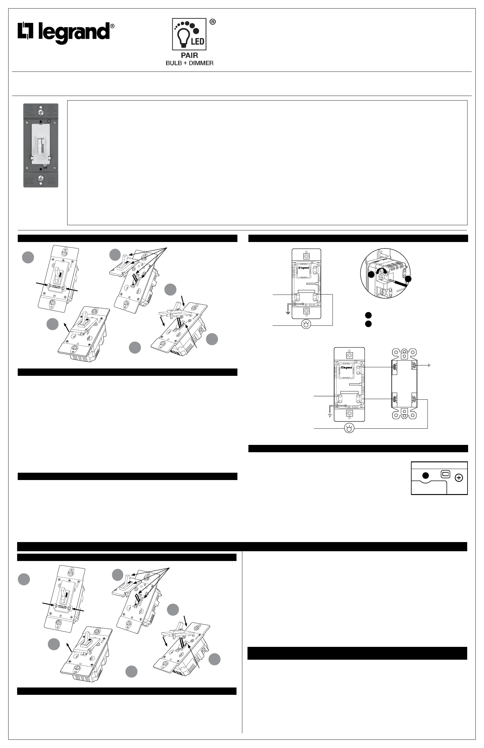
Figure 2 – Single Pole
Toggle, actuator, slider,
and lever must be in full
up position as shown
before installing the color
change kit
Snap down
cover making
sure slider is
engaged
Align toggle
and slider
Insert tabs
first
Press tabs
to remove
kit
1
2
3
4a
4c
Remove
4b
3-WAY
SINGLE POLE
COMMON
GR
TURN OFF POWER
Traveler Wire to
3-Way Switch
3-Way Switch
Hot
Neutral
Load
Traveler Wire to
3-Way Switch
Ground
Ground
Figure 3 – 3-Way
L’interrupteur, l’actionneur,
la glissière et le levier
doivent être dans la position
complètement en haut comme
il est indiqué avant d’installer
la trousse de changement.
Enclencher le
couvercle en
s’assurant que
la glissière est
enclenchée
Aligner
l’interrupteur et
la glissière
Insérer d’abord les
languettes
Appuyer
sur les
languettes
pour retirer
la trousse
1
2
3
4a
4c
La retirer
4b
Screw Pressure Plate Back Wire
1
Insertwiretobottomofhole.
2
Torqueterminalscrewsto14-16inchlbs.
Terminationtakes#12or#14AWGstrandedor
solid,copperconductors.
2
1
CAL