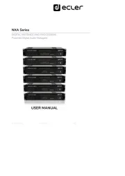
Ecler NXA6-200 Manual
Læs nedenfor 📖 manual på dansk for Ecler NXA6-200 (29 sider) i kategorien Modtager. Denne guide var nyttig for 38 personer og blev bedømt med 4.5 stjerner i gennemsnit af 19.5 brugere
Side 1/29

50 0257 01- - 11 EN NXA SERIES
NXA Series
DIGITAL MATRIXES AND PROCESSORS
Powered Digital Audio Managers
USER MANUAL

2
INDEX
1 IMPORTANT REMARK............................................................................................................. 3
2 IMPORTANT SAFETY INSTRUCTIONS ............................................................................... 4
3 IMPORTANT NOTE ................................................................................................................... 5
4 INTRODUCTION ........................................................................................................................ 5
4.1 Main features of NXA Series ................................................................................................ 6
5 INSTALLATION.......................................................................................................................... 7
5.1 Location, assembly, ventilation ........................................................................................... 7
5.2 Mains connection ..................................................................................................................... 8
5.3 Signal input connections ....................................................................................................... 8
5.4 Output connections ................................................................................................................ 9
5.5 Ethernet and RS- 232 ports.................................................................................................. 9
5.5.1 Factory Preset Network settings ............................................................................. 9
5.6 GPI remote control ports ..................................................................................................... 10
5.7 Connecting the GPI remote control ports ...................................................................... 10
5.8 FAULT port (equipment self-diagnosis) ......................................................................... 11
6 OPERATION AND USAGE .................................................................................................... 11
6.1 Start up ..................................................................................................................................... 11
6.2 Front panel LED indicators ................................................................................................. 11
6.3 Front panel controls .............................................................................................................. 13
7 CLEANING................................................................................................................................. 14
8 DIAGRAMS and FUNCTION LIST ....................................................................................... 14
9 BLOCK DIAGRAM ................................................................................................................... 15
10 TECHNICAL CHARACTERISTICS ....................................................................................... 16
11 TP- NET PROTOCOL INTRODUCTION .............................................................................. 20
12 NXA DIGITAL AUDIO MANAGER SERIES ........................................................................ 24
13 ERROR CODES FOR ECLERNET DEVICES ....................................................................... 28
13.1 COMMON ERROR CODES (to all EclerNet - - TP NET compatible devices)........ 28
13.2 NXA SERIES SPECIFIC ERROR CODES ........................................................................ 28

3
1 IMPORTANT REMARK
The lightning flash with arrowhead symbol, within an equilateral triangle, is
intended to alert the user to the presence of uninsulated “dangerous voltage”
within the product’s enclosure that may be of sufficient magnitude to
constitute a risk of electric shock to persons.
The exclamation point within an equilateral triangle is intended to alert the user
to the presence of important operating and maintenance (servicing)
instructions in the literature accompanying the appliance.
WARNING (If applicable): The terminals marked with symbol of “ ” may be of
sufficient magnitude to constitute a risk of electric shock. The external wiring connected
to the terminals requires installation by an instructed person or the use of ready-made
leads or cords.
WARNING: To prevent fire or shock hazard, do not expose this equipment to rain or
moisture.
WARNING: An apparatus with Class I construction shall be connected to a mains
socket-outlet with a protective earthing connection.

4
2 IMPORTANT SAFETY INSTRUCTIONS
1. Read these instructions.
2. Keep these instructions.
3. Heed all warnings.
4. Follow all instructions.
5. Do not use this apparatus near water.
6. Clean only with dry cloth.
7. Do not block any ventilation openings. Install in accordance with the
manufacturer’s instructions.
8. Do not install near any heat sources such as radiators, heat registers, stoves, or
other apparatus (including amplifiers) that produce heat.
9. Do not defeat the safety purpose of the polarized or grounding type plug. A
polarized plug has two blades with one wider than the other. A grounding type
plug has two blades and a third grounding prong. The wide blade or the third
prong are provided for your safety. If the provided plug does not fit into your outlet,
consult an electrician for replacement of the obsolete outlet.
10. Protect the power cord from being walked on or pinched particularly at the plugs,
convenience receptacles, and at the point where they exit from the apparatus.
11. Only use attachments/accessories specified by the manufacturer.
12. Unplug the apparatus during lightening sorts or when unused for long periods of
time.
13. Refer all servicing to qualified personnel. Servicing is required when the apparatus
has been damaged in any way, such as power supply cord or plug is damaged,
liquid has been spilled or objects have fallen into the apparatus, the apparatus has
been exposed to rain or moisture, does not operate normally, or has been dropped.
14. Disconnecting from mains: When switching off the POWER switch, all the
functions and light indicators of the unit will be stopped, but fully disconnecting
the device from mains is done by unplugging the power cable from the mains input
socket. For this reason, it always shall remain easily accessible.
15. Equipment is connected to a socket-outlet with earthing connection by means of
a power cord.
16. The marking information is located at the bottom of the unit.
17. The apparatus shall not be exposed to dripping or splashing and that no objects
filled with liquids, such as vases, shall be placed on apparatus.
WARNING: This product must not be discarded, under any circumstance, as
unsorted urban waste. Take to the nearest electrical and electronic waste
treatment centre.
NEEC AUDIO BARCELONA, S.L. accepts no liability for any damage that may be caused
to people, animal or objects due to failure to comply with the warnings above.

5
3 IMPORTANT NOTE
Thank you for choosing one of our Powered Digital Audio Managers, NXA Series !
It is VERY IMPORTANT to carefully read this manual and to fully understand its
contents before any connection in order to maximize your use and get the best
performance from this equipment.
To ensure optimal operation of this device, we strongly recommend that its maintenance
be carried out by our authorised Technical Services.
All ECLER products are covered by warranty, please refer to www.ecler.com or the
warranty card included with this product for the period of validity and conditions.
4 INTRODUCTION
The NXA series consists of four models with 4 channels and two models with 6 channels:
• NXA4-80: 4 x 80 W RMS @ 4
• NXA4-200: 4 x 200 W RMS @ 4
• NXA4-400: 4 x 420 W RMS @ 4
• NXA4-700: 4 X 730 W RMS @ 4
• NXA6-80: 6 x 80 W RMS @ 4
• NXA6-200: 6 x 200 W RMS @ 4
All models are equipped with cooling, without fan, a feature allowing a very convection
quiet operation, suitable for installation in noise sensitive environments.
The output (amplified) channels can work independently or paired, two operating modes
being then available: BRIDGE (one pair behaves as a single higher power amplifier) or
PARALLEL (one pair has two amplified outputs, but both receive and deliver identical
signals, simultaneously managed).
It also incorporates significant technological innovations regarding digital processing and
remote management via Ethernet and RS 232, making it the perfect candidate to -
undertake mobile applications and fixed installations, centralized or distributed, requiring
highly integrated remote control and monitoring with standard Ethernet networks.
NXA units are delivered with an internal DSP processing module and matrix functions, as
well as EclerNet remote management, that allows the physical connection of the amplifier
to an Ethernet network and its remote management and monitoring from anywhere on
this one, using EclerNet Manager (*) Windows® application. Please refer to the EclerNet
Manager software manual at www.ecler.com for more information.

6
4.1 Main features of NXA Series
• 4/6 analogue audio inputs
• 4/6 amplified output channels (SINGLE (independent), PARALLEL or BRIDGED
modes)
• 4/6 GPI remote control ports (compatible with 0-10VDC analogue devices, such as
Wpa WpaVOL and VOL-SR wall panels). A GPI port can control one or more inputs
or outputs (volume) or manage the recall of presets 1 to 5 (GPI- 1 only)
• Class D amplifiers (optimal energy consumption)
• Auto stand by function (optimal energy consumption)-
• 100% silent, thanks to unforced convection cooling (no fan)
• First class digital audio codecs, with excellent signal- - to noise ratio
• Ethernet interface, supporting EclerNet Manager software platform and UCP (User
Control Panels) web server web client remote control system-
• RS- 232 Interface
• TP-NET external remote control protocol, via Ethernet and RS-232 (compatible
with Crestron®, AMX®, RTI®, VITY®, etc..)
• POWER ON / OFF button and / or front panel volume controls can be deactivated
by software, preventing unauthorized tampering
• Front panel volume controls are assignable to one or more audio inputs or one or
more amplified outputs
• Self-diagnosis function for correct operation of the amplifier, with FAULT relay:
allows the device failure detector to switch to an external redundant system
• Integrated "Anti- clip" system
• Rack format (2RU)
• Integrated DSP processor, configurable from EclerNet Manager. Main functions:
o Each channel has a dedicated audio input mixer that enables you to generate
a separate mix from the ones made in the other channels
o Independent controls per channel: VOLUME, MUTE, SOLO, PHASE
INVERSION, MAX. VOL (upper volume limit) and MIN. VOL (lower volume
limit)
o LP and HP crossover filters, up to 4th order, per channel
o Bank of 8 parametric EQ filters, per channel
o Compressor with THRESHOLD, COMP. RATIO, ATTACK, RELEASE, KNEE
and MAKE UP GAIN settings, per channel-
o Delay, up to 1000 milliseconds, per channel
o DUCKER function (priority): an input can be configured with highest priority,
being able to reduce and replace the audio content of any channel, when its
signal exceeds the detection threshold. This feature is vital in emergency /
evacuation systems, which should play a specific alarm message and / or
evacuation instead of the regular audio program when detecting an
emergency scenario
o 5 configuration memories (presets) are available
* EclerNet Manager software is available on www.ecler.com

8
5.2 Mains connection
NXA series products are powered by 110- -120, 220 240VAC, 47 / 63Hz, depending on
the country (see nameplate on the device).
The mains cables must not be near the shielded cables carrying the audio signal, as this
could cause humming.
5.3 Signal input connections
NXA series rear panel provides analog, balanced, line level signal inputs. The selection of
hardware inputs and their routing and mixing towards either amplifier channel is
performed from the EclerNet Manager control application. Please refer to the EclerNet
Manager software manual at www.ecler.com for more information.
Signal input connectors are 3 position screw terminal block (7). The wiring is:
HOT or direct signal > Pin +
COLD or inverted signal > Pin -
GROUND > Pin ⊥
For unbalanced connection short- -. circuit pin ⊥to pin
STACK -outputs (8) available for inputs 1 and 2 are parallel to the input and serve to re
send the signal of these inputs ( ) to other input channels, amplifiers INPUTS, CH1 / CH2
or sound systems.
The input impedance is 22K (balanced). This impedance makes possible to parallel Ω
several amplifiers without loosing audio quality.

9
5.4 Output connections
The rear panel OUTPUTS section is fitted with two position screw terminal block (9) for
each amplifier channel (4 or 6, depending on model). Always respect the relative polarity
for outputs (+ and on each output connector), wiring and speakers. In bridge mode, -
follow the wiring and polarity standard indicated near the output screw terminal block
and labeled as "BRIDGE".
SINGLE / PARALLEL / BRIDGE operating modes are selected from EclerNet Manager
control application. Please refer to the EclerNet Manager software manual at
www.ecler.com for more information.
The connection cable that joins the amplifiers outputs and the loudspeakers must be of
good quality, sufficient section and as short as possible. This is most important when the
distances to cover are long ones i.e. up to 10 meters it is recommended to use a section
not inferior to 2.5mm2 and for superior distances 4mm2.
5.5 Ethernet and RS 232 ports-
An RJ-45 connector (12) allows the connection to an Ethernet network and its
management from EclerNet Manager application, or its control from a third party
equipment, thanks to the TP- NET external control protocol.
A 3-pin Euroblock connector for the integrated RS-232 (11) interface also allows the
device remote control using the TP NET protocol.-
Please refer to the EclerNet Manager software manual at www.ecler.com. and TP-NET
protocol for more information.
5.5.1 Factory Preset Network settings
The factory default network settings for EclerNet Manager compatible devices are as
follows:
• IP: 192.168.0.100
• Mask: 255.255.255.0
• Gate: 192.168.0.1
• UDP Port: 2210

10
5.6 GPI remote control ports
The NXA series rear panel provides 4 or 6 (depending on the model) 0 10VDC remote -
control ports (13), labeled "GPI 1-6", to which you can connect analogue devices such as
the Wpa series wall panels. With the EclerNet Manager application, a function can be
assigned to each of these ports: a GPI port can control one or more inputs or outputs
(volume) or manage the presets #1-5 recall (GPI- 1 only).
The level of each amplifier channel or output volume is determined by the sum of values of:
• its front rotary control (if it has one assigned)
• its channel fader (slider) (in EclerNet Manager)
• its GPI remote control port (if it has one associated with its volume control)
5.7 Connecting the GPI remote control ports
By linking a remote port to a volume control, the amount of attenuation applied to the
assigned input(s) or output(s) can be determined using three types of external devices:
a) A potentiometer with a nominal
value between 10kΩ Ω and 50k (e.g.
WPa series wall panels).
b) Using a device that generates a
control voltage from 0 to 10V DC.
c) Using remote relays/dry contacts.
NOTE: You can connect up to 16 remote control ports in parallel to the same hardware
control potentiometer. Ground connections of all devices those ports belong to must be
joined.
The connection cables can be up to 500m long if a section of 0.5mm2 is used.
Consult the available accessories at your ECLER dealer or on
www.ecler.com

11
5.8 FAULT port (equipment self- diagnosis)
The rear panel FAULT connector (10) is a NO / NC dry contact linked to the self-diagnosis
function of the unit. This function measures from time to time if each amplifier channel is
indeed working properly and delivering the correct amplified program to its output
terminals. If the test result is correct, i.e. if the amplifier is perfectly operating, the FAULT
contact remains at its default position, adopted immediately after the boot sequence. If,
on the contrary, and for whatever reason, the amplifier is not functional or is not correctly
operating, the FAULT contact toggles (a closed contact opens and an opened contact
closes).
Thus, an external device can monitor whether a NXA device is working properly or not,
and in the latter case it can report the fault and / or switch to a redundant equipment.
You can activate this function from the EclerNet Manager application and determine the
integrity test frequency (every minute, every hour, etc.).
6 OPERATION AND USAGE
6.1 Start up
When the rear panel POWER switch (14) is pressed, the amplifier is powered by the
network and can be switched on, briefly holding the front POWER button (6) or remotely
from the EclerNet Manager application or with the TP-NET protocol.
In a complete audio installation, it is important to start up the equipment in the following
sequence: sound sources, mixer, equalizers, active filters, processors and finally power
amplifiers. To turn them off the sequence should follow an inverse pattern.
6.2 Front panel LED indicators
NXA series products have the following LEDs on their front panel:
• SP indicators (2): indicate a signal presence in the amplification channels. These
indicators light up when the input signal exceeds a -40dB threshold.
• CLIP / PROTECT indicators (4): (available only on models 4- - -200, 6 200, 4 400 and
4- 700).
They light up for two possible reasons:
o When the signal delivered to the speaker is close to the actual clipping
level. The CLIP detection system considers possible voltage fluctuations of
power supply, always giving a real indication even if they exist. It is normal
for CLIP indicators to be lit at the bass frequencies rhythm for high

12
operating levels, as these frequencies have the higher energy content. You
must take care that these indicators do not permanently light up during
normal operation of the equipment.
o To indicate the absence of signal at the amplified output of the unit in the
following cases:
During the startup process up to the end of the STANDBY time
necessary to stabilize the amplifier internal tensions, before being
finally operational.
The equipment enters protection mode if it detects a low frequency
signal that may damage the speakers, excessive internal
temperature, a short circuit at the amplified output or a possible
internal damage.
In any case, if these indicators permanently light up, it is a sign of
malfunctioning and its cause should be investigated.
• CLIP indicators (3): (available only on models 4- - 80 and 6 80)
They light up when the signal delivered to the speakers is near clipping. The CLIP
system considers possible voltage fluctuations of power supply, always giving a real
indication even if they exist. It is normal for CLIP indicators to be lit at the bass
frequencies rhythm for high operating levels, as these frequencies have the higher
energy content. You must take care that these indicators do not permanently light
up during normal operation of the equipment.
• DATA transfer indicator (5): blinks to indicate a data transfer activity between the
device and the remote control PC running EclerNet Manager.
Note: all front panel LEDs blink when the " " function is activated in EclerNetDevice Finder
Manager application. That’s useful for identifying a physical device from its virtual
counterpart in this application. EclerNet Manager software manual at Please refer to the
www.ecler.com for more information.

13
6.3 Front panel controls
The front panel includes a series of knobs and a on/off button.
The equipment can be locally switched on by holding down the POWER key until the
startup sequence begins. Shutdown also requires holding down the same key during a
brief period.
The POWER key has an integrated LED that lights up in orange when the amplifier is in
standby mode (STANDBY), in green during operation (ON), and in red during the startup
sequence or when the amplifier is in protection mode.
After turning on and once the boot sequence completed, the device is available for use in
normal conditions.
Each front panel LEVEL knob (4 or 6, depending on the model) can be linked to the volume
control of one or more audio inputs or one or more audio outputs of the unit. The linking,
like the other device setup settings, is made from the EclerNet Manager application.
Please refer to the EclerNet Manager software manual at www.ecler.com for more
information.
Moreover, the EclerNet Manager application allows the DSP processing management
(volume, phase, EQ, compression, delay, customised input mixes for each output channel,
priority or DUCKER function, etc..) for each channel, each channel being used
independently (SINGLE) or in pairs (BRIDGE, PARALLEL modes) and remotely managed
individually or by groups of channels and / or amplifiers from a remote Ethernet location.
In BRIDGE and PARALLEL modes, the output level control of each channel pair from a
front LEVEL knob is done using the first channel of the pair only (CHANNEL 1 for 1 & 2,
CHANNEL 3 for 3 & 4 and Channel 5 for 5 & 6).
GPI ports also allow to remote control the input or output volume from a potentiometer
or another external hardware device. Remember that the final level of each amplifier
channel or output volume is determined by the sum of values of:
• its front rotary control (if it has one assigned)
• its channel fader (in EclerNet Manager)
• its GPI remote control port (if it has one associated with its volume control)

14
7 CLEANING
The front panel should not be cleaned with dissolvent or abrasive substances because
silk-printing could be damaged. To clean it, use a soft cloth slightly wet with water and
neutral liquid soap; dry it with a clean cloth. Be careful that water never gets into the
amplifier through the holes of the front panel.
8 DIAGRAMS and FUNCTION LIST
1 Input attenuator
2 Signal present indicator, SP
3 Clip indicator, CLIP
4 Combined clip and protection
indicator, CLIP/PROT
5 Data transfer indicator, DATA
6 On / Off key, POWER ON
7 Input terminal block
8 Terminal block to other amplifiers,
STACK
9 Output terminal block
10 FAULT terminal block
11 RS- 232 terminal block
12 Ethernet port
13 Terminal block for remote control
device
14 Start- up switch
15 Mains socket

15
9 BLOCK DIAGRAM

16
10 TECHNICAL CHARACTERISTICS
NXA4 80-
NXA6 80-
NXA4-200
NXA6-200
NXA4 400-
NXA4 700-
POWER 20Hz-20kHz 1% THD
1 Channel @ 2Ω (RMS)
1220 W
1 Channel @ 4Ω (RMS)
85 W
84 W
202 W
218 W
426 W
730 W
1 Channel @ 8Ω (RMS)
51 W
49 W
121 W
126 W
230 W
406 W
All Channels @ 4Ω (RMS)
66 W
65 W
168 W
163 W
330 W
530 W
All Channels @ 8Ω (RMS)
43 W
42 W
107 W
105 W
205 W
327 W
1 Bridge channel @ 8 Ω(RMS)
160 W
158 W
383 W
395 W
760 W
1180 W
1 Bridge channel @ 4 Ω(RMS)
2070 W
Overall Voltage Gain
+26 / +32 dB
Frequency response (- - 1dB, 3dB)
10Hz – 25kHz
THD + Noise @ 1kHz Full power
<0.05%
<0.08%
Noise Floor (FFT) 20Hz – 20KHz
>100dB (110dB typ.)
Damping factor 1kHz @ 8Ω
>150
>140
>400
>350
>600
>200
Channel Crosstalk @ 1kHz
>75dB
Input connectors
Terminal block (Symmetrical)
Input CMRR/ref. Max. PWR
>50dB
Signal present indicator
Lit at – 40dBV
Output connectors
Terminal block
Anticlip limiter
Soft / Mid / Hard
Volume remote control
(0-10VDC) (0.1A max.) 0V = no attenuation / +10V = full attenuation
Remote control connectors
Terminal block
Mains
115V/230V. Voltage changed internally (NOT BY SWITCH)
POWER CONSUMPTION
(pink noise, 1/8 power @ 4ohm)
107VA
144VA
225VA
312VA
431VA
729VA
(pink noise, 1/3 power @ 4ohm)
208VA
290VA
490VA
684VA
948VA
1610VA
Stand- by mains consumption
<3W
GENERAL
Panel Dimensions
482.6x88mm
Depth(Handles and knobs
excluded)
373mm
373mm
373mm
373mm
373mm
423mm
Weight
9.2kg
10.2kg
12.6kg
14.1kg
16.0kg
19.0kg

17
DIGITAL
Processing:
A/D & D/A
24 bit, 48kHz. 115dB AKM Codec
DSP
32/64 bits
Latency
2ms
Analog Input headroom:
+18 dBV = +21dBu
Digital Input attenuator:
Stepless from – ∞to +0dB
Input Impedance:
Balanced, 22kΩ
Maximum Delay:
1s (343.4m) for each channel
Delay resolution:
20.8µs (6mm)
Compressor / Limiter:
Threshold
from - 36dBV to +18dBV
Ratio
1:1 to :1 (limiter)∞
Attack time
Auto or from 0.1ms to 500ms.
Release time
Auto or from 1ms to 5s.
Output peak voltage limiter:
Peak voltage upon model (auto settings)
From 10Vpk to 70Vpk
High & Low pass Crossover filters
Butterworth in 6/12/18/24dB/oct.
Bessel in 12/18/24dB/oct
Linkwitz- Riley in 12/24dB/oct.
Parametric Eq. types (8 max. per output)
- - Bypass / On Off all channels
- - - Param. Eq. 20Hz 20kHz; 60/+12dB; Q from =.3 to 200
- Low & High Shelf 6/12 dB/oct
- Low & High Pass 6/12 dB/oct.
- - All Pass 1/2 order
Built In signal generator
- Sine (20Hz to 20kHz)
- Polarity(10/20Hz to 10/20kHz)
- White
- Pink
Signal Mute
Yes
Signal Polarity Invert
Yes
Connectivity:
- - -Over, Cat5 Ethernet Base Tx 10/100Mb, Auto X
- -8-N-1-N RS232 57600(fixed)

18
SOFTWARE
EclerNet Software
- Realtime full GUI of all functions and controls thru Ethernet
with interactive graphical display
- Grouping mode channels or devices
- Automated report generation
- Remote power on with programmable delay.
- 256 devices on same net. Up to
- Autodiscovery devices feature
- Routing capability through NAT gateways.
- Real time metering at input/output (DSP)
- Device “Finder” feature
- Save & Recall setup and preset functions
- Firmware update capability thru Ethernet
- Password protection
- Default Network configuration:
IP: 192.168.0.100
Mask: 255.255.255.0
Gate: 192.168.0.1
UDP Port: 2210
Operating System:
Windows®: XP Prof. (SP3); Vista (SP1); W7(SP1), W8, W10
and W11.
Minimum EclerNet System Requirements:
Pentium IV ® 2GHz
500MB RAM
100MB HDD free space
1024x768 pixels & 16bits colour display
10/100/1000 Ethernet Network card

19
TP- NET PROTOCOL
SOFTWARE
Third- Party NET
USER MANUAL

20
11 - TP NET PROTOCOL INTRODUCTION
The TP-NET protocol lets a client device (control device) get and/or set the values of
several parameters of the EclerNet compatible devices (MIMO and MIMO SG series
digital matrices, DUO-NET PLAYER, NXA digital audio manager series, NZA amplifier
series, NPA amplifier series, etc.), like volumes, mutes, alarms, etc. It’s as well available
for eMIMO1616 digital matrix, HUB series digital zoner, MIMO7272DN and
MIMO4040CDN digital matrix.
The communication with these digital audio devices can be established using Ethernet
and the UDP/IP transport protocol, always by means of the 5800 UDP port.
A second option for this communication is using the RS-232 interface that some of these
compatible devices do also have (MIMO series, DUO NET PLAYER, NXA series, etc.). In -
this case, the serial connection must fulfil the following specifications:
• Baud rate: 57600 -(fixed, no autonegotiation) for all the devices, except for DUO
NET PLAYER, eMIMO1616, HUB series and MIMO4040CDN, which use 115200
baud rate)
• Data bits: 8
• Parity: None
• Stop bits: 1
• Flow control: None
In case the Ecler device has an Euroblock connector for the RS-232 interface, the serial
cable wiring, from the device’s connector to a standard DB9 serial interface connector,
must be the following:
The protocol is simple and direct, making it easy to read, write and modify the generated
code. It is based on messages with no begin and end delimiter: each message is self-
delimited by the UDP packet size, which is defined with a maximum of . All
80 characters
the messages must be written in capital letters.
To let some control systems (like CRESTRON®, EXTRON®, AMX®, RTI®, VITY®,
MEDIALON®, etc.) process the messages more easily, the EclerNet device adds the
character LF (0x0A) to the end of each message. This way the client can buffer the
messages to process them, if it’s required. The EclerNet device can also handle several
messages received in a single message packet by using the LF delimiter.

21
The available messages are built with one or more fields separated with blank spaces (
= blank space):
<TYPE> [PARAM1] [PARAM2] [PARAM3] [PARAM4][LF]
The first field (TYPE) defines the and then, the required parameters for it message type
(each kind of message requires a given number of parameters). The field TYPE can have
these values:
• SYSTEM
• GET
• SET
• INC
• DEC
• SUBSCRIBE
• UNSUBSCRIBE
• DATA
• ERROR
At the end of this document you’ll find all the available messages and their parameters
for each model of the EclerNet compatible devices.
The SYSTEM, GET, SET, INC, DEC, SUBSCRIBE & UNSUBSCRIBE messages can be sent
from the client to the EclerNet device. The DATA & ERROR messages can be sent from
the device to the client. The only exception is the SYSTEM PING message, that is a
SYSTEM type message that is sent from the EclerNet device when the initial message
from the client to the device was SYSTEM CONNECT PINGPONG.
The communication (using UDP or RS-232) starts when a client sends the message
SYSTEM CONNECT to the EclerNet device. As far as the UDP communication requires
no connection (unlike the TCP), the EclerNet device stores this client’s IP address, and
then uses it as the destination IP address for the messages that it generates (DATA &
ERROR). After receiving the SYSTEM CONNECT message, the device dumps its entire
configuration using several consecutive DATA messages.
Note: if the configuration data dump process (usually a huge list of parameters & values)
wants to be avoided after a SYSTEM CONNECT message, a SYSTEM CONNECT ONCE
message can be used instead.
The communication can be terminated by two methods:
• Manually: cancelling when the client sends the SYSTEM DISCONNECT message,
all the subscriptions and stopping the DATA & ERROR messages

22
• Automatically: in case the initial message was SYSTEM CONNECT PINGPONG
and the client didn’t get any SYSTEM PONG message in a period longer than 10
seconds (presuming a communication breakdown)
The SET messages don’t have an automatic acknowledgement with a DATA message
sent from the EclerNet device after it has processed the command. The client must SET
update the values itself and must send the needed message if it requires GET
confirmation from the device.
NOTES:
• The numerical values are always integer numbers without + –, , comma or dot
symbols.
• [PINGPONG] -is an optional parameter used to configure the device client
communication with a periodical check, to see whether the client or the device have
terminated it. When configured this way, the device sends a SYSTEM PING once
per second, and the client must answer with a message. If anyone SYSTEM PONG
doesn’t get these messages along a 10 seconds period, the communication will be
considered terminated.
• [ONCE] is an optional parameter used to start the device-client communication
without a full data dump process (usually a huge list of parameters & values).
• <Input Channel> & <Output Channel> are numerical values that identify an input
or output channel of the EclerNet device. For the NXA series it can be within the
[1..4] or [1..6] range, for 4 or 6 channel amplifiers.
• <Preset Number> is a numerical value that identifies one available Preset stored in
the EclerNet device’s memory. For the NXA and NZA series it can be within the
[1..5] range.
• <Level>, <Pre Vumeter Level> y <Post Vumeter Level> are numerical values in the
[0..100] range that define values in a scale equivalent to [- . inf..0] dB
• <GPI> & <GPO> . are numerical values For the NXA series GPI values can be within
the [1..4] or [1..6] range, depending on model.
• <GPI Value> is a numerical value within the [0..100] range that indicates the value
of an analogue GPI input. For a digital input only 0 or 100 are the possible values.
• <GPO Value> is a numerical value within the [0..1] range: it can only be 0 or 1
(opened or closed GPO).
• <Rate> -is a numerical value within the [1..10] range that sets the VU meter refresh
rate, or the number of times the vumeters’ values are sent per second (by default =
3).
• “<Device Name>” is the device name inside double quotation marks, to allow for
names with blank spaces.
• <Error ID> . is a numerical value for an error code

23
• “<Error Description>” is a text chain inside double quotation marks, containing an
error description.
• <Virtual Control> . is a numerical value that identifies a Virtual Control
o It can be within a [1A..4A] or [1B..4B] range for NXA 4 ch. Models.
o It can be within a [1A..6A] or [1B..6B] range for NXA 6 ch. M . odels

24
12 NXA DIGITAL AUDIO MANAGER SERIES
IMPORTANT NOTE: The communication must be started with the client sending the first message SYSTEM
ONCE to the EclerNet device. Otherwise, the commands from the client to the EclerNet device will be
INTRODUCTION chapter for additional information.
TYPE
PARAM1
PARAM2
PARAM3
PARAM4
DESCRIPTION
SYSTEM
CONNECT
[MASTER]
[PINGPONG]
[ONCE]
• MASTER: this parameter, applied in
disconnect all clients currently conn
and not correctly closed connection
way we guarantee that the client th
only one connected by TP NET to th-
• PINGPONG: this parameter can be
the difference is that this parameter
the communication is still open (PIN
no response, the communication ha
• ONCE: this parameter is used to pre
DISCONNECT
Cancel subscriptions and terminates c
SUBSCRIPTION_RATE
<Rate>
Alive message from device
PING
Alive message from device
PONG
Alive ACK message from client
GET
ALL
Dumps current device status (with DA
POWER
Gets the Device Power status
PRESET
Gets the current PRESET
OLEVEL
<Output
Channel>
Gets the current LEVEL of an Output
XLEVEL
<Input
Channel>
<Output
Channel>
Gets the current LEVEL of a Matrix po
OMUTE
<Output
Channel>
Gets the current MUTE status of an O

25
XMUTE
<Input
Channel>
<Output
Channel>
Gets the current MUTE status of a Ma
OVU
<Output
Channel>
Gets the VU meter value of an Outpu-
ALARM_PROTECT
<Output
Channel>
Gets the Protect alarm status of an O
ALARM_FAULT
<Output
Channel>
Gets the self-diagnosis system alarm
INFO_NAME
Gets the Device Name
INFO_MODEL
Gets the Device Model
INFO_VERSION
Gets the Firmware Version
INFO_MAC
Gets the Device MAC address
VIRTUAL_CONTROL
<Virtual
Control>
Gets the Virtual Control value

26
TYPE
PARAM1
PARAM2
PARAM3
PARAM4
SET
POWER
ON/OFF
Sets the Device P
PRESET
<Preset Number>
Sets the current P
OLEVEL
<Output Channel>
<Level>
Sets the current L
XLEVEL
<Input Channel>
<Output
Channel>
<Level>
Sets the current L
OMUTE
<Output Channel>
YES/NO
Sets the current M
XMUTE
<Input Channel>
<Output
Channel>
Sets the current M
VIRTUAL_CONTROL
<Virtual Control>
<Value>
Sets the Virtual C
to 100)
INC
OLEVEL
<Output Channel>
<Value>
Increases the curr
Value (Value can
XLEVEL
<Input Channel>
<Output
Channel>
<Value>
Increases the curr
(Value can range
DEC
OLEVEL
<Output Channel>
<Value>
Decreases the cu
Value (Value can
XLEVEL
<Input Channel>
<Output
Channel>
<Value>
Decreases the cu
Value (Value can
SUBSCRIBE
ALL
Subscribes to all V
OVU
<Output Channel>
Subscribes to an
UNSUBSCRIBE
ALL
Unsubscribe to al
OVU
<Output Channel>
Unsubscribe to an
DATA
POWER
ON/OFF
Shows the Device
PRESET
<Preset Number>
Shows the curren
OLEVEL
<Output Channel>
<Level>
Shows the curren
XLEVEL
<Input Channel>
<Output
Channel>
<Level>
Shows the curren
OMUTE
<Output Channel>
YES/NO
Shows the curren
XMUTE
<Input Channel>
<Output
Channel>
YES/NO
Shows the curren
VIRTUAL_CONTROL
<Virtual Control>
<Value>
Shows the Virtua

27
OVU
<Output Channel>
<Pre Vumeter
Level>
<Post Vumeter
Level>
Shows the VU-m
ALARM_PROTECT
<Output Channel>
ON/OFF
Shows the Protec
ALARM_FAULT
<Output Channel>
ON/OFF
Shows the self di-
Output Channel
INFO_NAME
“<Device Name>”
Shows the Device
INFO_MODEL
<Device Model>
Shows the Device
INFO_VERSION
<Firmware
Version>
Shows the Firmw
INFO_MAC
<Device MAC
address>
Shows the Device
ERROR
<Error ID>
“<Error
Description>”
Informs about an
Note: INC DEC and commands are replied with a DATA command from the device with the resulting LEVE
or decreased. When the INC or DEC command tries to adjust a LEVEL value beyond its minimum or maximu
will be produced.
Produkt Specifikationer
Mærke: | Ecler |
Kategori: | Modtager |
Model: | NXA6-200 |
Har du brug for hjælp?
Hvis du har brug for hjælp til Ecler NXA6-200 stil et spørgsmål nedenfor, og andre brugere vil svare dig
Modtager Ecler Manualer

1 Juni 2025

31 Maj 2025

30 Januar 2025

30 Januar 2025

5 Januar 2025

5 Januar 2025

3 Januar 2025

3 Januar 2025

3 Januar 2025

3 Januar 2025
Modtager Manualer
- Modtager Salus
- Modtager Sonos
- Modtager Raymarine
- Modtager Bugera
- Modtager Audizio
- Modtager Fontastic
- Modtager Cisco
- Modtager Galaxy Audio
- Modtager Alpine
- Modtager Marmitek
- Modtager Roksan
- Modtager Inateck
- Modtager Logitech
- Modtager Kramer
- Modtager Simrad
Nyeste Modtager Manualer

8 Juni 2025

8 Juni 2025

8 Juni 2025

8 Juni 2025

8 Juni 2025

8 Juni 2025

8 Juni 2025

8 Juni 2025

8 Juni 2025

8 Juni 2025