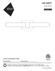
Elan Caputo 84321 Manual

Elan Lettelse Caputo 84321

Læs gratis den danske manual til Elan Caputo 84321 (3 sider) i kategorien Lettelse. Denne vejledning er vurderet som hjælpsom af 20 personer og har en gennemsnitlig bedømmelse på 4.9 stjerner ud af 10.5 anmeldelser. Har du et spørgsmål om Elan Caputo 84321, eller vil du spørge andre brugere om produktet?

Side 1/3
For warranty informaon please visit: kichler.com/warranty
Fixture Diagram
Parts List
Cauons
CAUTION – RISK OF SHOCK –
Disconnect Power at the main circuit breaker panel or main
fusebox before starng and during the installaon.
WARNING:
Thisxture is intended for installaon in accordance
with the Naonal Electrical Code (NEC) and all local code
specicaons. If you are not familiar with code requirements,
installaon by a cered electrician is recommended.
DIMMING:
This LED xture is compable with most standard
incandescent dimmers, LED dimmers, and electronic low
voltage dimmers.
For opmal performance, an electronic low voltage dimmer
should be used.
See kichler.com/dimming for a list of compable dimmers.
CLEANING:
• Always be certain that electric current is turned o before
cleaning.
• Only a so damp cloth should be used. Harsh cleaning
products may damage the nish.
[A] Outlet Box
[B] Lockup Knob
[C] Hexnut
[D] Mounting
Strap
[E] Canopy
[F] Strap
Mounting
Screw
[G] Threaded
Pipe
1) Take threaded pipe[G] from parts bag and screw on
hexnut[C] a minimum of 13 mm (1/2”) as shown.
2) Screw threaded pipe into mounng strap unl hexnut [D]
prevents the pipe from screwing any further. Mounng
strap must be posioned with extruded thread facing
into outlet box as shown. Threaded pipe must [A]
protrude out the back of mounng strap far enough
to fully engage second hexnut. If necessary, adjust the
posion of rst hexnut on threaded pipe to ensure full
engagement of second hexnut.
3) Screw second hexnut onto end of threaded pipe
protruding from back of mounng strap. Hexnut should
be screwed down onto threaded pipe unl mounng
strap prevents the hexnut from screwing any further.
4) Aach mounng strap[D] to outlet box[A] using the
strap mounng screws . Mounng strap can be [F]
adjusted to suit posion of xture.
5) Grounding instrucons: (See Illus. a or b).
a) On xtures where mounng plate is provided with a
hole and two raised dimples, wrap ground wire from
outlet box around green ground screw, and thread
into hole.
b) On xtures where a cupped washer is provided,
aach ground wire from outlet box under cupped
washer and green ground screw, and thread into
mounng plate.
If xture is provided with ground wire, connect xture
ground wire to outlet box ground wire with wire
connector aer following the above steps. Never connect
ground wire to black or white power supply wires.
6) Make wire connecons. Reference chart below for
correct connecons and wire accordingly.
Connect Black or Red
Supply Wire to:
Connect White Supply
Wire to:
Black White
*Parallel cord (round &
smooth)
*Parallel cord (square &
ridged)
Clear, Brown, Gold or
Black without Tracer
Clear, Brown, Gold or Black
with Tracer
Insulated wire (other
than green) with copper
conductor
Insulated wire (other
than green) with silver
conductor
*Note: When parallel wire (SPT
1 & SPT 2) are used. The neutral
wire is square shaped or ridged
and the other wire will be round
in shape or smooth (See illus.) Neutral Wire
7) Raise xture to ceiling, carefully passing threaded pipe
aached to mounng strap through center hole in
canopy[E].
8) Screw lockup knob onto threads protruding through [B]
hole in center of canopy.
GREEN GROUND
SCREW
CUPPED
WASHER
OUTLET BOX
GROUND
FIXTURE
GROUND
DIMPLES
WIRE CONNECTOR
OUTLET BOX
GROUND
GREEN GROUND
SCREW
FIXTURE
GROUND
a b
Installaon Instrucons
This device complies with part 15 of the FCC Rules. Operaon is subject to the following two
condions:
1) This device may not cause harmful interference, and
2) This device must accept any interference received, including interference that may cause
undesired operaon.
Note: This equipment has been tested and found to comply with the limits for a Class B digital
device, pursuant to part 15 of the FCC Rules. These limits are designed to provide reasonable
protecon against harmful interference in a residenal installaon. This equipment generates,
uses and can radiate radio frequency energy and, if not installed and used in accordance with
the instrucons, may cause harmful interference to radio communicaons. However, there is
no guarantee that interference will not occur in a parcular installaon. If this equipment does
cause harmful interference to radio or television recepon, which can be determined by turning
the equipment o and on, the user is encouraged to try to correct the interference by one or
more of the following measures:
Reorient or relocate the receiving antenna.
Increase the separaon between the equipment and receiver.
Connect the equipment into an outlet on a circuit dierent from that to which the
receiver is connected.
Consult the dealer or an experienced radio/TV technician for help.
FCC Informaon:
IS-84321-US
We’re here to help 866-558-5706
Hrs: M-F 9am to 5pm EST
REV 26-MAR-2021
G
D
E
C
A
F
C
B
13 mm (1/2”)
G
D
E
C
A
F
C
B
Pour de plus amples informaons sur la garane, veuillez visiter : kichler.com/warranty
1) Prendre le tuyau leté[G] dans le sac de pièces et visser
sur l’écrou hexagonal[C] à un minimum de 13 mm (1/2
po) tel qu’illustré.
2) Visser le tuyau leté dans l’étrier de montage[D] jusqu’à
ce que l’écrou hexagonal empêche le tuyau d’être vissé
plus à fond. Létrier de montage doit être posionné pour
que l’extrémité letée soit face au boîer électrique[A]
tel qu’illustré. Le tuyau leté doit émerger de l’arrière
de létrier de montage susamment pour que l’écrou
hexagonal puisse y être vissé solidement. Au besoin,
ajuster la posion du premier écrou hexagonal sur le
tuyau leté pour garanr que lécrou hexagonal peut
être vissé solidement.
3) Visser le deuxième écrou hexagonal sur l’extrémité
du tuyau leté qui émerge de larrière de l’étrier de
montage. Lécrou hexagonal devrait être vissé sur le
tuyau leté jusqu’à ce que létrier de montage empêche
le tuyau d’être vissé plus à fond.
4) Aacher l’étrier de montage au boîer électrique[D] [A]
à laide des vis de létrier de montage . Létrier de [F]
montage peut être ajusté selon la posion du luminaire.
5) Connecter les ls. Se reporter au tableau ci-dessous pour
faire les connexions.
Connecter le l noir ou
rouge de la boite Connecter le l blanc de
la boîte
A Noir A Blanc
*Au cordon parallèle (rond
et lisse)
*Au cordon parallèle (à
angles droits el strié)
Au transparent, doré,
marron, ou noir sans l
disncf
Au transparent, doré,
marron, ou noir avec un l
disncf
Fil isolé (sauf l vert) avec
conducteur en cuivre Fil isolé (sauf l vert) avec
conducteur en argent
*Remarque: Avec emploi d’un
l paralléle (SPT 1 et SPT 2). Le
l neutre est á angles droits ou
strié et lautre l doit étre rond
ou lisse (Voir le schéma). Fil Neutre
6) Soulevez le luminaire jusqu’au plafond, en passant avec
précauon le tube leté aaché à létrier de montage
par le trou central du cache .[E]
7) Vissez le bouton de verrouillage sur les letages [B]
dépassant du trou central du cache.
Diagramme d’appareils
ATTENTION – RISQUE DE DÉCHARGES ÉLECTRIQUES -
Couper le courant au niveau du panneau du disjoncteur du
circuit principal ou de la boîte à fusibles principale avant de
procéder à l’installaon.
ATTENTION:
Ce luminaire doit être installé conformément aux codes
d’électricité naonaux (NEC) et sasfaire toutes les
spécicaons des codes locaux. Si vous ne connaissez pas
les exigences de ces codes, il est recommandé de coner
l’installaon à un électricien ceré.
GLAGE DE LINTENSITÉ :
Ce luminaire à DEL est compable avec la plupart des
gulateurs d’intensité pour ampoules incandescentes,
gulateurs d’intensité pour DEL, et régulateurs d’intensité
électroniques basse tension.
Pour une performance opmale, un régulateur d’intensité
électronique basse tension devrait être ulisé.
Consulter kichler.com/dimming pour obtenir une liste de
gradateurs compables.
NETTOYAGE :
• Soyez toujours certain que lalimentaon électrique du
luminaire est fermée avant le neoyage.
• Nulisez qu’un chion doux humide. Les produits de
neoyage acides/abrasifs peuvent endommager leni.
Liste des Pièces
Précauons
Instrucons d’installaon
[A] Boîtier
Électrique
[B] Bouton de
Verrouillage
[C] Écrou
Hexagonal
[D] Étrier de
Montage
[E] Cache
[F] Vis de Létrier
de Montage
[G] Tuyau Fileté
Cet appareil est conforme à la secon 15 de la réglementaon de la FCC. L’exploitaon est
soumise aux deux condions suivantes :
1) Cet équipement ne doit pas causer d’interférences nuisibles, et
2) Cet équipement doit accepter toute interférence reçue, y compris les interférences
risquant d’engendrer un fonconnement indésirable.
Remarque: Des tests ont conrmé que ce matériel respecte les limites d’un disposif nurique
de catégorie B, en vertu de la secon 15 de la réglementaon de la FCC. Ces limites ont été
conçues pour fournir une protecon raisonnable contre le brouillage nuisible d’une installaon
résidenelle. Cet équipement génère, ulise et peut rayonner de lénergie radiofréquence et,
s’il n’est pas installé et ulisé selon les instrucons, peut causer de l’interférence nuisible aux
communicaons de radio. Cependant, il est néanmoins possible qu’il y ait de l’interférence dans
une installaon en parculier. Si cet équipement cause du brouillage nuisible à la récepon
du signal de radio ou delévision, ce qui peut être déterminé en éteignant puis en rallumant
l’appareil, lusager peut essayer de corriger l’interférence en appliquant une des mesures
suivantes :
orienter l’antenne de récepon ou changer son emplacement.
Augmenter la distance séparant l’équipement et le récepteur.
Brancher le matériel dans la prise de courant d’un circuit diérent de celui auquel le
récepteur est branché.
Consulter le revendeur ou un technicien radio/télé dexrience.
FCC Informaon:
IS-84321-CB
Nous sommes là pour vous aider 866-558-5706
Heures : du lundi au vendredi, de 9h à 17h (heure de l’Est)
INSTRUCTIONS:
For Assembling and Installing Fixtures in Canada
Pour Lassemblage et L’installaon Au Canada
REV 26-MAR-2021
13 mm (1/2 po)


Produkt Specifikationer

Mærke: Elan
Kategori: Lettelse
Model: Caputo 84321

Har du brug for hjælp?

Hvis du har brug for hjælp til Elan Caputo 84321 stil et spørgsmål nedenfor, og andre brugere vil svare dig