Electia IRA-8 Manual

Electia Alarm IRA-8

Læs gratis den danske manual til Electia IRA-8 (8 sider) i kategorien Alarm. Denne vejledning er vurderet som hjælpsom af 45 personer og har en gennemsnitlig bedømmelse på 3.7 stjerner ud af 23 anmeldelser. Har du et spørgsmål om Electia IRA-8, eller vil du spørge andre brugere om produktet?

Side 1/8
IRA-8
OWNERS MANUAL
A
Ar
rt
t.
.
3
36
6.
.2
28
87
72
2
G
GB
B
P
PI
IR
R
M
Mo
ot
ti
io
on
n
S
Se
en
ns
so
or
r
(
(I
IR
RA
A-
-8
8)
)
The PIR picks up movements within an assigned area and signals the Control Panel to activate the alarm if an intruder
crosses its’ path of detection.
The PIR consists of a two-part design made up of a cover and a base. The cover contains all the electronics and optics
and the base provides a means of fixing. The base has knockouts to allow mounting on either a flat surface or in a corner
situation with fixing screws and plugs provided.
Provision for a tamper switch that will be activated when the cover is detached from the base prevents unauthorized access
and removal from the mounting surface. The PIR can also alert you to signal communication problems and low battery
situations.
The PIR is designed to give a typical detection range of 12 meters when mounted at 2 meters above ground.
I
Id
de
en
nt
ti
if
fy
yi
in
ng
g
t
th
he
e
p
pa
ar
rt
ts
s.
.
Remove the cover by loosening the button fixing screw, the inside of the PIR will revealed as shown.
Learn/Test Button
1
This button is used for testing the radio performance and for learning
purpose.
Tamper Switch
2
The Tamper switch protects the enclosure from being opened.
Test/Normal Mode Jumper Switch (JP1)
3
It is a 3-pin jumper switch
If the jumper link is in inserted between the left 2 pins, the PIR is
in Test mode.
If the jumper link is inserted between the right 2 pins, the PIR is in
Normal operation mode.
S
Su
up
pe
er
rv
vi
is
si
io
on
n
F
Fu
un
nc
ct
ti
io
on
n
When the PIR is in Normal operation mode it will conduct a Self-test Periodically by transmit a supervisory signal
once every 50 sec to 90 sec.
If the Control Panel can’t receive the Supervisory signals transmitted from a certain PIR, an Out-Of-Order” fault
message will be generated.
S
Sl
le
ee
ep
p
T
Ti
im
me
er
r
The PIR has a sleep timeof approximately 1 minute to conserve power. After transmitting a detected movement,
the PIR will not retransmit for 1 minute; any further movement detected during this sleep period will extend the sleep
time by another minute. In this way continuous movement in front of a PIR will not unduly exhaust the battery.
T
Te
es
st
t
m
mo
od
de
e
The PIR can be put into Test mode by inserting the jumper link between the left two pins of the Test mode jumper
switch. In Test mode, it will disable the sleep timer and will enable the LED indicator to flash every time a movement
is detected.
<<NNOOTTEE>>
The jumper must not be left in this position in normal use; otherwise battery life will be shortened and the
local low battery display will not be able to be seen.
L
LE
ED
D
I
In
nd
di
ic
ca
at
to
or
r
There is a LED Indicator behind the lens on the right upper corner. In Normal operation mode, the LED Indicator will
not light except in the following situations:
When the PIR is in low battery condition, every time it transmits a detected movement, the LED will flash for
about 2 seconds.
When the cover is opened and the tamper switch is violated, the LED will flash for 2 sec. to indicate it is
transmitting the “ ” signal. Tamper
When the Tamper condition persists, every time it transmits a detected movement, the LED will flash.
However, if the PIR is in Test mode, the LED will flash every time a movement is detected.
B
Ba
at
tt
te
er
ry
y
The PIR use two 1.5V AA” alkaline batteries as its power source. The PIR will have a typical battery life of over 2
years at an average of 50 activations a day.
Low battery detection operates at a threshold of 2.2V+/-10% where the PIR has enough reserve energy to typically
operate for 1 month before complete exhaustion. The low battery signal will be sent to the Control Panel along with
regular signal transmissions for the Control Panel to display the status accordingly.


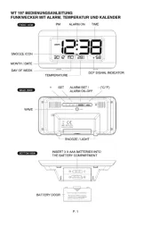
Produkt Specifikationer

Mærke: Electia
Kategori: Alarm
Model: IRA-8

Har du brug for hjælp?

Hvis du har brug for hjælp til Electia IRA-8 stil et spørgsmål nedenfor, og andre brugere vil svare dig