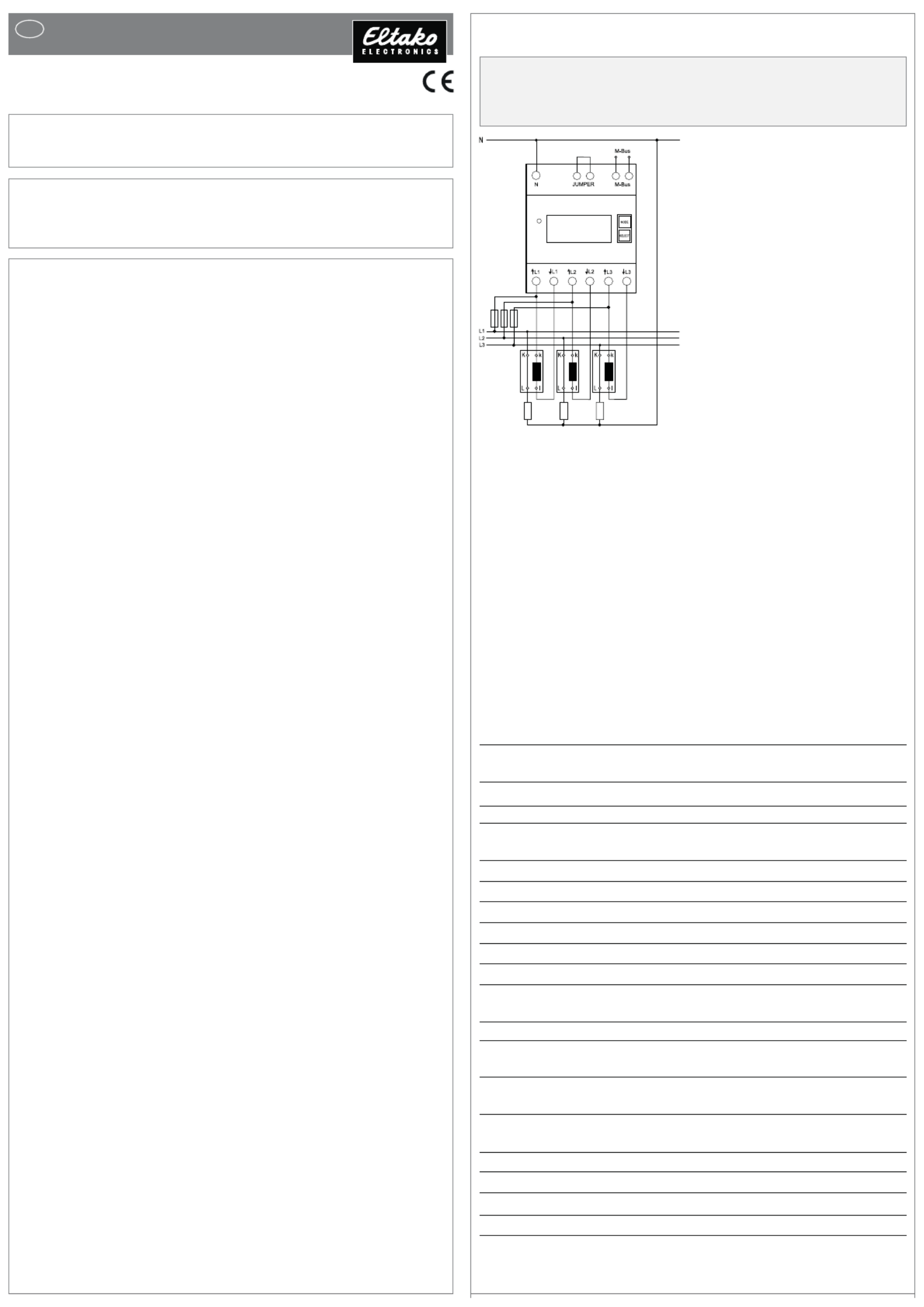
Eltako DSZ15WDM-3x5A Manual
| Mærke: | Eltako |
| Kategori: | Måling |
| Model: | DSZ15WDM-3x5A |
Har du brug for hjælp?
Hvis du har brug for hjælp til Eltako DSZ15WDM-3x5A stil et spørgsmål nedenfor, og andre brugere vil svare dig
Måling Eltako Manualer

7 Januar 2024

12 November 2023

17 December 2022
Måling Manualer
- Phoenix Contact
- ClimeMET
- Gossen Metrawatt
- Kimo
- REV
- Megger
- Triplett
- Parkside
- Hama
- ENTES
- Voltcraft
- Gossen
- Cablexpert
- Hazet
- Schneider
Nyeste Måling Manualer

4 November 2025

3 November 2025

3 November 2025
2 November 2025
2 November 2025
1 November 2025

31 Oktober 2025

31 Oktober 2025

31 Oktober 2025
31 Oktober 2025