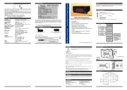
2.2 Panel Cut-Out
2. General Descr�pt�on
2.1 Front V�ew and D�mens�ons of EPM-3790 Un�t
EPM-3790N 77x35 DIN S�ze
Control Panel For V/F Speed Controller
Instruct�on Manual. ENG EPM-3790-N 01 V03 07/23
Operat�ng Temperature : 0 to 50 °C
Max. Operat�ng Hum�d�ty : 90 Rh (non-condens�ng)
:Alt�tude Up to 2000m
Forb�dden Cond�t�ons:
Corros�ve atmosphere
Explos�ve atmosphere
Home appl�cat�ons (The un�t �s only for �ndustr�al appl�cat�ons)
1.2 General Spec�f�cat�ons
1 Preface
2
1.1 Operat�ng Cond�t�ons
3 41615
13 14
EPM-3790N
Power Supply Input
D�g�tal Input
110 mm / 4.33 �nch (m�n)
50 mm / 1.97 �nch (m�n)
29 mm / 1.14 �nch
71 mm / 2.79 �nch
1.3 Installat�on
1.4 Warranty
1.5 Ma�ntenance
1.6 Manufacturer
Mount�ng Clamp
Panel surface
Max�mum th�ckness 15 mm / 0.59 �nch
76 mm / 3 �nch
6 mm / 0.24 �nch
34,5 mm / 1.36 �nch
65 mm / 2.56 �nch
Error Input
EPM-3790N
SET
9. Order�ng Informat�on
A BC D E FG HI /
/
U
V W Z/
/
0 00 1 0 0
EPM-3790N
00 0
(77 x 35 DIN S�ze)
RS-485 Commun�cat�on Interface
1.RS-485 Module
2. PROKEY Programm�ng Module
Your technology partner
www.emkoelektronik.com.tr
EPM-3790N
7. Motor Start / Stop Operat�on
EPM-3790N
SET
i
8. Spes�f�cat�ons
Dev�ce Type
Hous�ng & Mount�ng
Protect�on Class
We�ght
Env�ronmental Rat�ng
Storage / Operat�ng Temperature
Storage / Operat�ng Hum�d�ty
Installat�on
Overvoltage Category
Pollut�on Degree
Scale
Analogue Output
Resolut�on
Supply Voltage and Power
D�splay
LEDs
: Control Panel For V/F Speed Controller
: 77mm x 35mm x 62.5mm Plast�c hous�ng for panel
Mount�ng. Panel cut-out �s 71x29mm.
: Approx�mately 200 grams
: Standard, �ndoor at an alt�tude of less than 2000 meters
w�th none-condens�ng hum�d�ty.
: F�xed Installat�on
: II.
: II. Off�ce or workplace, none conduct�ve pollut�on
: Between -1999 and 9999
: 12 b�ts
: 10 mm red 4 d�g�ts LED
:Compl�ances
: -40 C to +85 C / 0 C to +50 C
: 90 % max. (None condens�ng)
: NEMA 4X (IP65 at front, IP20 at rear).
: 0/2...10VZ Voltage Output (Max.10mA) or
0/4...20mAZ Current Output
D�g�tal Output
: Forward D�rect�on Output (Max. 5mA@30V)
Reverse D�rect�on Output (Max. 5mA@30V)
D�g�tal Input
: Error Input (Max. 5mA@30VZ)
M�n. H�gh Level 7VZ )
Max. Low Level 5VZ )
Fluctuat�on
: 30 mV
0
9. Opt�onal Accessor�es
SET
Standard
D�g�tal Output
In accordance w�th the WEEE regulat�on.
Please leave the dev�ce to a recycl�ng po�nt for electr�cal dev�ces.
: 230VV(±%15) 50/60Hz - 2.5VA
: 115VV(±%15) 50/60Hz - 2.5VA
: 24VV(±%15) 50/60Hz - 2.5VA
: 24VW(±%15) 50/60Hz - 2.5VA
: 10 - 30VZ- 2.5W
- 4 D�g�ts D�splay
- Adjustable dec�mal po�nt
- Set value low l�m�t and set value h�gh l�m�t boundar�es
- Adjustable ramp up and ramp down t�me
- Eas�ly adjustable set value from front panel
- Conf�gurable d�splay scale between -1999 and 9999
- Forward, Reverse d�rect�on outputs and error �nput for V/F Speed
Controller
- 0/2...10V Z Voltage output or 0/4...20mA Z Current output
(It must be spec�f�ed �n order.)
- Password protect�on for programm�ng and sett�ngs sect�ons
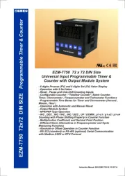
EPM-3790N 77x35 DIN S�ze
Control Panel For V/F Speed Controller
EPM-3790-N ser�es un�ts are des�gned for controll�ng the speed and d�rect�on of the motor as
a control panel for V/F Speed Controllers �n �ndustry. They can be used �n many appl�cat�ons
w�th the�r easy use and operat�on w�th the�r ramp propert�es.
Un�versal Supply Input
230V V (±%15) 50/60Hz
Opt�onal Supply Input
115V V (±%15) 50/60Hz
24V V (±%15) 50/60Hz
24V W (±%15) 50/60Hz
10 - 30V Z
Forward D�rect�on Output
Reverse D�rect�on Output
Analogue Output
(0/2...10V Z)
Analogue Output
(0/4...20mA Z)
Reference Speed for
V/F Speed Controller
Front Panel
IP65 protect�on
NEMA 4X
Before beg�nn�ng �nstallat�on of th�s product, please read the �nstruct�on manual and
warn�ngs below carefully.
c
Th�s package conta�ns
- A dev�ce un�t
- Two p�eces of mount�ng clamps
- An �nstruct�on manual
A v�sual �nspect�on of th�s product for poss�ble damage occured dur�ng sh�pment �s recommended before
�nstallat�on. It �s your respons�b�l�ty to ensure that qual�f�ed mechan�cal and electr�cal techn�c�ans �nstall th�s product.
If there �s danger of ser�ous acc�dent result�ng from a fa�lure or defect �n th�s un�t, power off the system and the
electr�cal connect�on of the dev�ce from the system.
The un�t �s normally suppl�ed w�thout a power supply sw�tch or a fuse. Use power sw�tch and fuse as requ�red.
Be sure to use the rated power supply voltage to protect the un�t aga�nst damage and to prevent fa�lure.
Keep the power off unt�l all of the w�r�ng �s completed so that electr�c shock and trouble w�th the un�t can be
prevented.
Never attempt to d�sassemble, mod�fy or repa�r th�s un�t. Tamper�ng w�th the un�t may results �n malfunct�on, electr�c
shock or f�re.
Do not use the un�t �n combust�ble or explos�ve gaseous atmospheres.
Dur�ng the equ�pment �s putted �n hole on the metal panel wh�le mechan�cal �nstallat�on some metal burrs can cause
�njury on hands, you must be careful.
Installat�on of the product on a system must be done w�th the prov�ded f�x�ng clamps. Do not attempt to �nstall the
dev�ce w�th �nappropr�ate f�x�ng clamps. Make sure to keep the dev�ce steady dur�ng the �nstallat�on.
It �s your respons�b�l�ty �f th�s equ�pment �s used �n a manner not spec�f�ed �n th�s �nstruct�on manual.
EMKO Elektron�k warrants that the equ�pment del�vered �s free from defects �n mater�al and workmansh�p. Th�s warranty �s
prov�ded for a per�od of two years. The warranty per�od starts from the del�very date. Th�s warranty �s �n force �f duty and
respons�b�l�t�es wh�ch are determ�ned �n warranty document and �nstruct�on manual performs by the customer completely.
Repa�rs should only be performed by tra�ned and spec�al�zed personnel. Cut power to the dev�ce before access�ng �nternal
parts. Do not clean the case w�th hydrocarbon-based solvents (Petrol, Tr�chlorethylene etc.). Use of these solvents can
reduce the mechan�cal rel�ab�l�ty of the dev�ce. Use a cloth dampened �n ethyl alcohol or water to clean the external plast�c
case.
Manufacturer Informat�on:
Emko Elektron�k Sanay� ve T�caret A.Ş.
Bursa Organ�ze Sanay� Bölges�, (Feth�ye OSB Mah.)
Al� Osman Sönmez Bulvarı, 2. Sokak, No:3 16215
BURSA/TÜRKİYE
Phone : +90 224 261 1900
Fax
: +90 224 261 1912
Repa�r and Ma�ntenance Serv�ce Informat�on:
Emko Elektron�k Sanay� ve T�caret A.Ş.
Bursa Organ�ze Sanay� Bölges�, (Feth�ye OSB Mah.)
Al� Osman Sönmez Bulvarı, 2. Sokak, No:3 16215
BURSA/TÜRKİYE
Phone : +90 224 261 1900
Fax : +90 224 261 1912
A
Power Supply
2
3
5
8
4
9
Customer Spec�f�ed
24VW (±%15) 50/60Hz - 2.5VA
24VV (±%15) 50/60Hz - 2.5VA
115VV (±%15) 50/60Hz - 2.5VA
230VV (±%15) 50/60Hz - 2.5VA
10 - 30V Z - 2.5W
5
Voltage Output (0/2...10V Z max. 10 mA)
Output
E
Current Output (0/4...20mA Z)
4
All order �nformat�on of EPM-3790N un�ts are g�ven on the table above. User may form
appropr�ate dev�ce conf�gurat�on from �nformat�on and codes that at the table and convert �t
to the order�ng codes. F�rstly, supply voltage then other spec�f�cat�ons must be determ�ned.
Please f�ll the order code blanks accord�ng to your needs. Please contact us, �f your needs
are out of the standards.
Please set the parameters accord�ng to des�red cond�t�ons before operat�ng the dev�ce.
Improperly conf�gured dev�ce may cause hazard.
Module for upload�ng and download�ng
the user parameters
V Symbol means Vac,
Z Symbol means Vdc,
Please don't d�spose the dev�ce along w�th other waste at the end of �ts serv�ce l�fe.
Thank you for your �nterest �n EMKO Elektron�k
products. In order to download a more deta�led vers�on
of th�s manual, please v�s�t us at our webs�te.
: (red), (red), (red), (red), (green), (green)
When Start/Stop button �s pressed, Set value �s seen on d�splay, Start led l�ghts on, selected
d�g�tal output �s be�ng act�ve and analogue output starts to �ncrease from the set low l�m�t
value to set value dur�ng Tup(sec) t�me w�th ramp.
Wh�le the motor �s runn�ng �f Start/Stop button �s pressed aga�n set low l�m�t value �s seen on
d�splay, Start led l�ghts off, analogue output starts to decrease from set value to set low l�m�t
value dur�ng Tdown(sec) t�me. When analogue output �s equal to set low l�m�t value selected
d�g�tal output �s be�ng �nact�ve.
It �s val�d, �f the dev�ce type 0/2...10V
It �s val�d, �f the dev�ce type 0/4...20mA
Z
Z
analogue output.
analogue output.
If no operat�on �s performed �n programm�ng mode for 20
seconds, dev�ce turns to operat�on screen automat�cally.
(1)
(2)
Error Detect�on for
V/F Speed Controller
Forward, Reverse D�rect�on
Control for V/F Speed Controller
Protect�on Aga�nst
Mechan�cal Impacts : 1Joule (IK06)
,
,