Emko EPR-3790-N Manual
Emko
Ikke kategoriseret
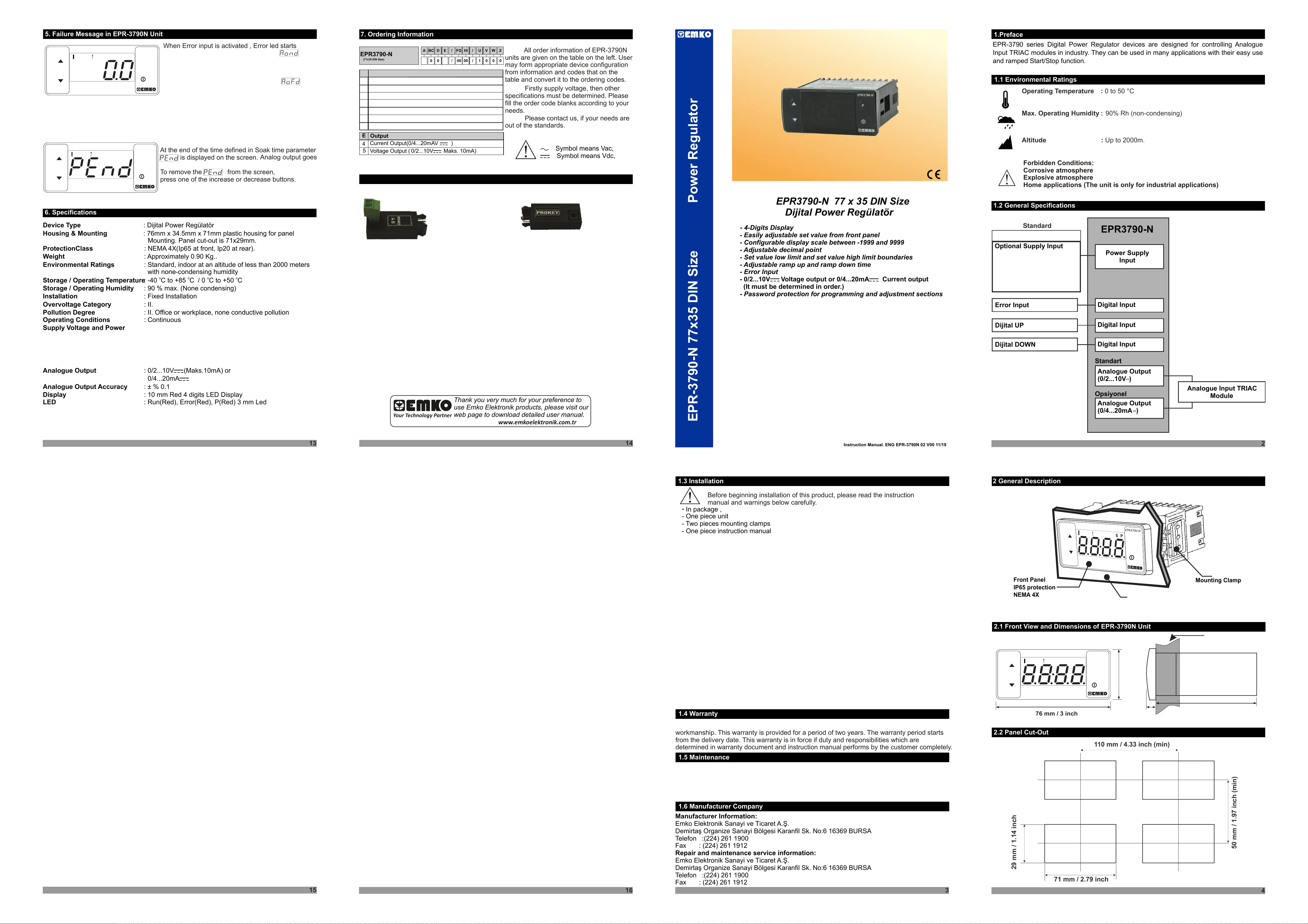
EPR-3790-N
| Mærke: | Emko |
| Kategori: | Ikke kategoriseret |
| Model: | EPR-3790-N |
Har du brug for hjælp?
Hvis du har brug for hjælp til Emko EPR-3790-N stil et spørgsmål nedenfor, og andre brugere vil svare dig
Ikke kategoriseret Emko Manualer
8 September 2025
8 September 2025
8 September 2025
8 September 2025
8 September 2025
8 September 2025
8 September 2025
8 September 2025
8 September 2025
7 September 2025
Ikke kategoriseret Manualer
- Taramp’s
- Rockford Fosgate
- Patching Panda
- Morrison
- Terratec
- Taylor
- Cardo
- Bleep Labs
- Hecate
- Dobar
- Cambro
- Joby
- Chieftec
- BRIO
- Cleveland
Nyeste Ikke kategoriseret Manualer

4 November 2025

4 November 2025

4 November 2025

4 November 2025

4 November 2025

4 November 2025

4 November 2025

4 November 2025

4 November 2025

4 November 2025