5. ChangingandSavingTemperatureSetValue
6.1DefrostZamanýSetDeðerininDeðiþtirilmesiveKaydedilmesi
MainOperationScreen
WhenIncrementorDecrementbutton
pressedSET expressionisshownon
display,afterrelasingthepressed
button‘’S’’ ledwillbeactiveand
temperaturesetvaluewillbedisplayed.
SETValueScreen
Temperaturesetvaluecan
bechangedwithincrement
anddecrementbuttons.
WhenCompressor buttonpressed
temperaturesetvaluecanbesaved.
‘’S’’ willbeinactiveandgoesbackto
mainoperationscreen.
MainOperationScreen
Temperaturesetvalueparameter(Default=18)
Temperaturesetvalue
°C.
,canbeprogrammedbetweentemperaturesetminimumparameter
Valueandmaximumtemperaturesetvalue50
230 V ±15%
50/60Hz-1.5VA
V
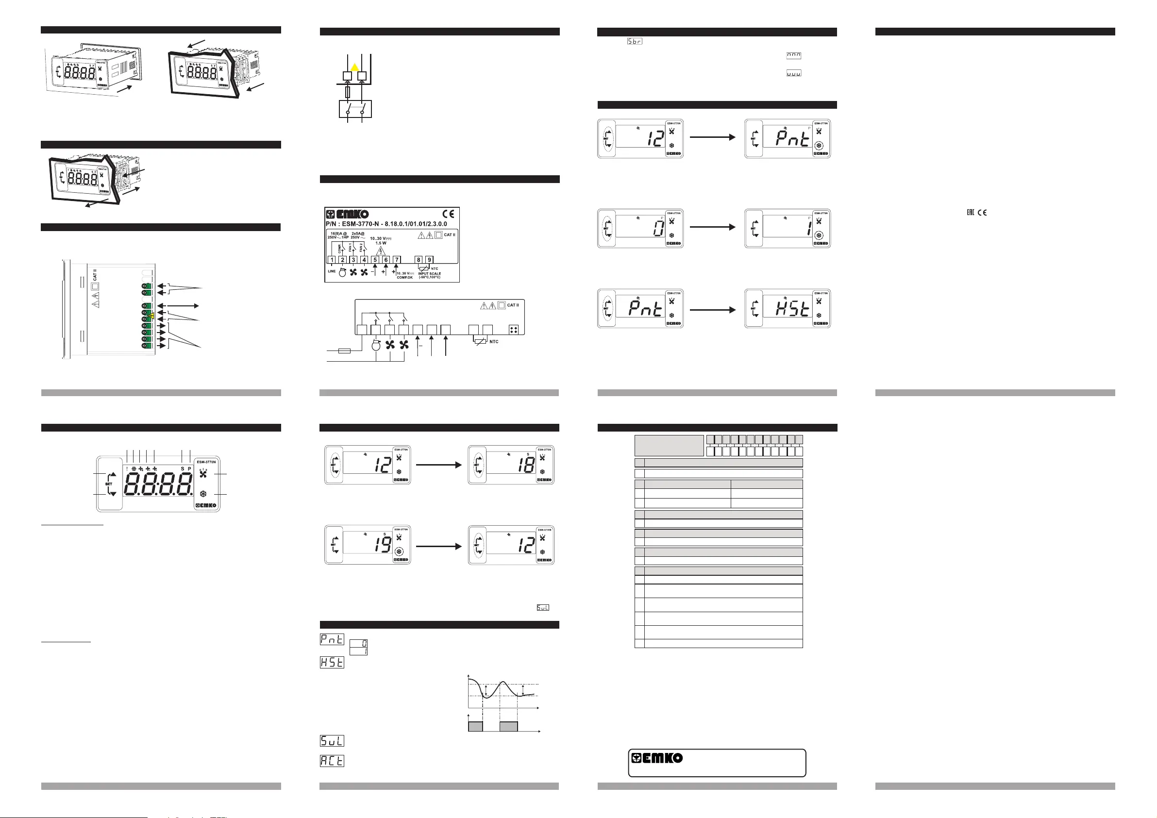
3.2DeviceLabelandConnectionDiagram
3.1SupplyVoltageInputConnectionoftheDevice
Note-1 : External fuse is recommended.
Make sure that the power supply voltage is the same
indicated on the instrument.
Switch on the power supply only after that all the electrical
connections have been completed.
Supply voltage range must be determined in order. While
installing the unit, supply voltage range must be controlled
and appropriate supply voltage must be applied to the unit.
c
There is no power supply switch on the device. So a power
supply switch must be added to the supply voltage input.
Power switch must be two poled for seperating phase and
neutral, On/Off condition of power supply switch is very
important in electrical connection.
External fuse that on power supply inputs must be on
phase connection.
External fuse that on power supply inputs must be on (+)
connection.
V
Z
c
10-30VZ CONNECTION DIAGRAM
4.FrontPanelDefinitionand AccessingtotheMenus
BUTTON DEFINITIONS
LED
1. Increment Button :
2. Decrement Button :
3. Compressor Button:
4. Fan Button:
5. Compressor Failure led :
6. Compressor output led :
7.Fan II led :
8.Fan I led :
9.Fan 0 led :
10.Set led :
** It is used to increase the value in the Set screen and Programming mode.
** In main operation screen; if this button pressed SET
** It is used to decrease the value in the Set screen and Programming mode.
** In main operation screen; if this button pressed SET
** , it is used to saving parameter.
**
** In main operation screen; if this button pressed Fan outputs are can be activated with
sequentialy.
** It is used to exit from Set screen and Programming mode to main operation screen without
aving parameter.
**
**
**
** 1
** ive.
**
S
is shown on the display, after releasing
the pressed button set value is shown on the display and SV led becomes active.
is shown on the display, after releasing
the pressed button set value is shown on the display and SV led becomes active.
in the Set screen and Programming mode
In main operation screen, it is used to activated compressor output.
It is active when compressor failure statuses.
This led indicates that compressor output is active
This led indicates that 2. Fan output is active
This led indicates that . Fan output is active
This led indicates that all fan outputs are pass
Indicates that device is in Set value changing mode.
**Blinks in programming mode .
DEFINITIONS
11.Program led :
5
8
10
9
5 6 9 10
121187
1-Cihazýn montaj yapýlacaðý panel kesitini,
verilen ölçülerde hazýrlayýnýz.
2-Cihazý panel üzerindeki kesite yerleþtiriniz.
Cihazýn montaj aparatlarý üzerinde ise panel
üzerine yerleþtirmeden çýkarýnýz.
3-Montaj aparatlarýný yanlardaki sabitleme
yuvalarýna yerleþtirip cihazý panele sabitleyiniz.
3
1- ok yönünde bastýrarýnýz.
2-Y geriye
doðru
3-Cihazý panelin ön tarafýndan çekerek çýkarýnýz.
Montaj aparatlarýný,
anlardaki sabitleme yuvalarýndan hafifçe
çekerek çýkartýnýz.
Cihazý panel üzerinden ayýrma iþlemine
baþlamadan önce cihazýn ve baðlý olduðu
sistemin enerjisini kesiniz, cihazýn tüm
baðlantýlarýný ayýrýnýz.
c
2.4RemovingfromthePanel
1
3
5.1 ProgrammingModeParameterList
Hysteresis Parameter for Compressor Output ( Default = 1 )
This parameter can be adjusted between 0 and %50 of device scale.
In ON/OFF control algorithm, temperature
value is tried to keep equal to set value by
opening or closing the last control element.
ON/OFF controlled system, temperature
value oscillates continuously. Temperature
value’s oscillation period or amplitude around
set value changes according to controlled
system. For reducing oscillation period of
temperature value, a threshold zone is formed
below or around set value and this zone is
named hysteresis.
ON
OFF
Temperature
Control
Output
Set
HSt
Time
HSt
Time
Compressor Stop-Start Delay Parameter
When compressor is inactive, this time delay must be expired for activation of the
compressor. It can be adjusted from 0 to 99 seconds.
(Default =0)
Decimal Seperator Enabling Parameter ( Default = 0 )
Disable
Enable
c
a
Note-1
5
6
-
+
3
2
1
2
10...30 V 1.5 WZ
WhenIncrementorDecrement
buttonispressedfor5seconds,
“P”ledstartstoblink.
MainOperation
Pressincrementbuttonforaccessing
tothenextparameter,press
decrementbuttonforaccessingto
thepreviousparameter.
5.3 EnteringToTheProgrammingMode,ChangingandSavingParameter
1. Blinking expression on display. Sensor failure. Wrong sensor connection or sensor
break.
5.2FailureMessageonESM-3770NDevice
3.ElectricalWiringDiagram
5
6
7
8
9
Comp.OK
a
2x5A@250V V
16(8)A
@250V 1HPV
2
3
41
COMP.
FAN 1
FAN 2
L
N
+
16A TSigorta
2
1
3
5
4
6
7
8
9
P/N: ESM-3770-N
a
CompressorOK
10
Z...30V
10...30 V 1.5 WZ
ProgrammingScreen
Presscompressorbuttonforaccessingto
theparametervalue.Pressincrementbutton
foraccessingtothenextparameter,press
decrementbuttonforaccessingtothe
previousparameter.
Changethevaluewith
incrementanddecrement
buttons.
DecimalSeperator
EnablingParameter
Presscompressorbuttonfor
savingtheparameter.
DecimalSeperator
EnablingParameter
DecimalSeperator
EnablingParameter
HysteresisParameter
2. If temperature value is over the scale high limit, temperature value and displayed on
screen with sequentialy.
6
7
DeviceType
Housing&Mounting
ProtectionClass
Weight
EnvironmentalRatings
Storage/OperatingTemperature
Storage/OperatingHumidity
Installation
OvervoltageCategory
PollutionDegree
OperatingConditions
emperatureSensorInput
Inputtype
SensorBreakProtection
SamplingCycle
ControlForm
RelayOutputs
:CoolingController
:76mmx34.5mmx71mmplastichousingforpanel
Mounting.Panelcut-outis71x29mm.
:(Ip65atfront,Ip20atrear
: Approximately0.20Kg.
:Standard,indooratanaltitudeoflessthan2000meters
withnonecondensinghumidity.
:-40 Cto+80 C/-30 Cto+80 C
:90%max.(Nonecondensing)
:Fixedinstallation
:II.
:II,officeorworkplace,noneconductivepollution
:Continuous
±1%offullscaleforthermoresistance
:Upscale
:3samplespersecond
:ON/OFF
forResistiveload
Electricallife100.000switchingatfullload)
forResistiveload
Green
o o o o
SupplyVoltageandPower
T
NTCInputtype
PTC
Accuracy
Gösterge
LEDgöstergeler
UyumluStandartlar
:10-30
:NTC(10k @25°C)
:PTC(1000 @25°C)
:
: A@250V (Compressoroutput)
( :
A@250V (Fanoutputs)
:14mmRed4digitLEDDisplay
:S(Green),P ( ),FanOFF(Yellow),FanI(Red),FanII
(Red),FailureInput(Red),CompressorOutput(Red)
:,
:NTC,PTC
W
W
16(8)
5
V
V
V 1.5WZ
6. Specifications
All order information of ESM-3770-N Cooling Controller are given on the upper table. User may form
appropriate device configuration from information and codes that at the table and convert it to the
ordering codes. Firstly, supply voltage then other specifications must be determined. Please fill the order
code blanks according to your needs.
Please contact us, if your needs are out of the standards.
7. OrderingInformation
A BC D E FG HI /
/
U
V W Z/
/
0 2 0 0
1
Relayoutput(16(8) A@250V ,1NO)Vatresistiveload
CompressorOutput
E
PowerSupplyA
InputType
BC
Scale(°C)
ESM-3770-N
-50°C 150°C
12
PTC(Note-1)
Temp.SensorwhichisgivenwithESM-3770-N
V
0
None
3
NTC-M5L20.K1.5(NTCSensor,thermoplastic mouldedwith
1.5mcable forcooling application)
4
NTC-M6L50.K1.5(NTCSensor,stainless steel housing with
1.5mcable forcooling application)
9
Customer
1 1
8
10-30V Z
-50°C 100°C
18
NTC(Note-1)
1
PTC-M6L40.K1.5(PTC AirProbewith1.5mtsiliconcable)
2
PTCS-M6L30.K1.5.1/8”(PTCLiquidProbewith1.5mtsiliconcable)
(77x35DINSize)
1
Relayoutput atresistiveload(5A@250V ,1NO)V
FanIOutput
FG
1
Relayoutput atresistiveload(5 A@250V ,1NO)V
FanIIOutput
HI
Minimum Temperature Set Value Parameter
Temperature set value can not be lower than this value.
This parameter value can be adjusted between °C and °C.
(Default =10 )
(-10 ) 50
Note:If no operation is performed in temperature set value changing mode for 3 seconds, device
turns to main operation screen automatically and saved set value.
NOTE: Ifnooperationisperformedinprogrammingmodefor20seconds,deviceturnsto
mainoperationscreenautomatically..
+
10..30VZ
10..30 V
1.5W
Z
8 1
3
4
1
2
SETValueScreen
INPUTSCALE
(-50°C,100°C)
2.3PanelMounting
RelayOutput
TemperatureSensor
Input (NTCorPTC)
SupplyVoltageInput
PowerSupplyConnection
EXTERNAL
FUSE
(1A T)
Supply
Switch
Supply Voltage
11
3. If temperature value is under the scale low limit, temperature value and displayed on
screen with sequentialy.
YourTechnologyPartner
www.emkoelektronik.com.tr
Thankyouverymuchforyourpreferenceto
useEmkoElektronikproducts,pleasevisitour
webpagetodownloaddetailedusermanual.