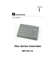
EverFocus EFC-02-1A Manual
Læs gratis den danske manual til EverFocus EFC-02-1A (75 sider) i kategorien Ikke kategoriseret. Denne vejledning er vurderet som hjælpsom af 117 personer og har en gennemsnitlig bedømmelse på 4.8 stjerner ud af 59 anmeldelser.
Har du et spørgsmål om EverFocus EFC-02-1A, eller vil du spørge andre brugere om produktet?
Produkt Specifikationer
| Mærke: | EverFocus |
| Kategori: | Ikke kategoriseret |
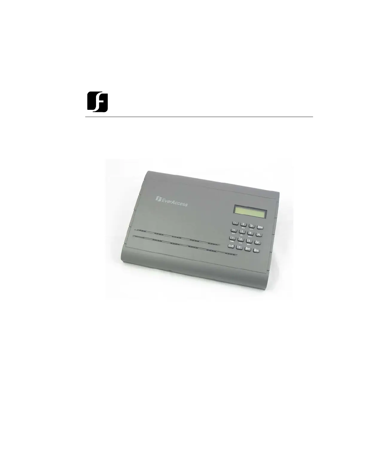
| Model: | EFC-02-1A |
| Bredde: | 300 mm |
| Dybde: | 216 mm |
| Højde: | 33 mm |
| Strømforbrug (typisk): | 30 W |
| Grænseflade: | RS-232 / RS-485 |
| Boks design: | Kabinet |
| Maksimale antal døre: | 8 dør(e) |
| Programmerbare begivenheder: | 16000 |
| Antal programmerbare helligdage: | 10 |
| Maksimal PIN længde: | 4 |
| Omstillelig DC spænding: | 12 V |
Har du brug for hjælp?
Hvis du har brug for hjælp til EverFocus EFC-02-1A stil et spørgsmål nedenfor, og andre brugere vil svare dig
Ikke kategoriseret EverFocus Manualer

Ikke kategoriseret Manualer
- Riviera And Bar
- Epson
- Aerotec
- Phil & Teds
- Dash
- Uni-T
- Ugears
- JET
- Parklands
- Nord
- Victory
- DaVoice
- SABO
- Draper
- Gaslock
Nyeste Ikke kategoriseret Manualer


