1
FOX3 SR 321, FOX3 SR 331, and FOX3 SR 211 • Setup
Guide
IMPORTANT NOTE:
Go to www.extron.com for the complete user guide, installation instructions, and specications
before connecting the product to the power source.
FOX3 SR 321 FOX3 SR 331 FOX3 SR 211
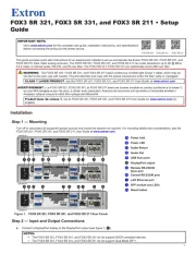
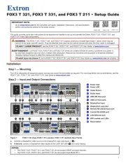
This guide provides quick start instructions for an experienced installer to set up and operate the Extron FOX3 SR 321, FOX3 SR 331, and
FOX3 SR 211 Fiber Optic scaling receivers. The FOX3 SR 321, FOX3 SR 331, and FOX3 SR 211 can scale resolutions up to 4K @ 60Hz,
4:4:4 video, 2-channel audio, RS-232, and IR over ber. The FOX3 SR 321, FOX3 SR 331 can additionally send USB over ber.
WARNING: The FOX3 SR 321, FOX3 SR 331, and FOX3 SR 211 output continuous invisible light (Class 1 rated), which may be
harmful to the eyes; use with caution. Plug the attached dust caps into the optical transceivers when the ber cable is unplugged.
CLASS 1 LASER PRODUCT, see the FOX3 SR 321, FOX3 SR 331, and FOX3 SR 211 User Guide, at www.extron.com.
AVERTISSEMENT : Le FOX3 SR 321, FOX3 SR 331, et FOX3 SR 211 émet une lumière invisible en continu (conforme à la classe 1)
qui peut être dangereux pour les yeux, à utiliser avec précaution. Associez les bouchons anti-poussière à l’ensemble émetteur/
récepteur optique lorsque le câble bre optique est débranché.
Produit laser de classe 1, voir le FOX3 SR 321, FOX3 SR 331, and FOX3 SR 211 User Guide sur www.extron.com (en
anglais).
Installation
Step 1 — Mounting
Turn o or disconnect all equipment power sources and mount the receiver as required. For mounting details and considerations, see the
FOX3 SR 321, FOX3 SR 331, and FOX3 SR 211 User Guide at www.extron.com.
50-60 Hz
100-240V
~
--A MAX
LR
LR
RS-232
Tx Rx Tx RxG
IR
A
OUT
R
IN
OUTPUTS
AUDIO
RETURN
INPUTS
CONTROL
B
OUT
IN
DISPLAYPORT
AUDIO
FOX3 SR 331
LAN
1
2
100 mA
REMOTE
RS-232
Tx Rx S5VG
3D
SYNC
USB HID
DEVICES
50-60 Hz
100-240V
~
--A MAX
LR
LR
RS-232
Tx Rx Tx RxG
IR
A
OUT
R
IN
OUTPUTS
AUDIO
RETURN
INPUTS
CONTROL
B
OUT
IN
DISPLAYPORT
USB 2.0
AUDIO
FOX3 SR 321
LAN
1
1
2
100 mA
REMOTE
RS-232
Tx Rx S5VG
3D
SYNC
DEVICES
USB HID
500 mA
1
J
I
IG
G
C
C
B
BA
A
H
H
D
D
J
J
F
F
E
E
FOX3 SR 331
K
K
50-60 Hz
100-240V
~
--A MAX
LR
LR
RS-232
Tx Rx Tx RxG
IR
A
OUT
R
IN
OUTPUTS
AUDIO
RETURN
INPUTS
CONTROL
B
OUT
IN
DISPLAYPORT
AUDIO
FOX3 SR 211
LAN
REMOTE
RS-232
Tx Rx S5VG
3D
SYNC
I
IG
GC
CB
BA
A
H
H
D
D
J
J
F
F
K
K
FOX3 SR 211
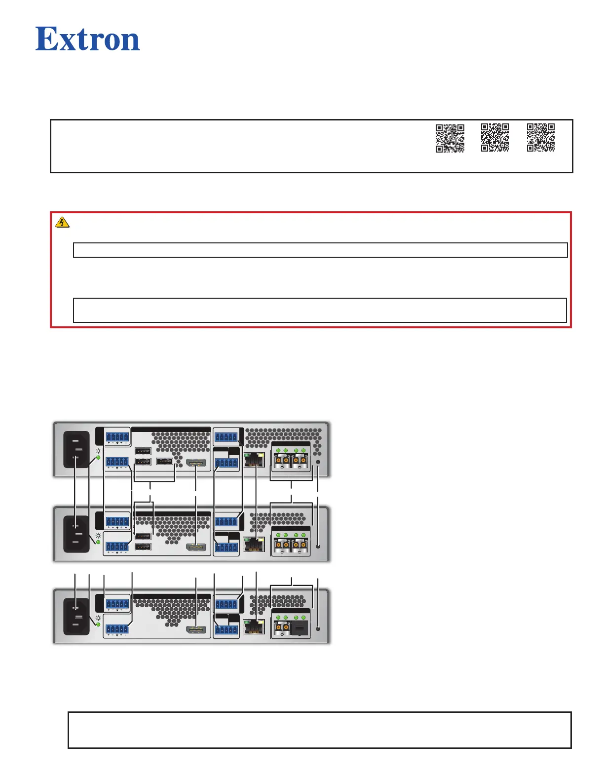
Figure 1. FOX3SR321, FOX3SR331, and FOX3SR211 Rear Panels
A
Power Inlet
B
Power LED
C
Audio Return
D
Audio Out
E
USB Hub ports
F
DisplayPort output
G
Remote RS-232/3D
Sync port
H
Control RS-232/IR port
I
LAN Ethernet port
J
SFP module and LEDs
K
Reset button
Step 2 — Input and Output Connections
a. Connect a DisplayPort display to the DisplayPort output (see figure 1,
F
).
NOTES:
• The FOX3 SR 321, FOX3 SR 331, and FOX3 SR 211 do not support HDCP-compliant devices.
• The FOX3 SR 321, FOX3 SR 331, and FOX3 SR 211 do not support Dual-Mode DP++.
1