1
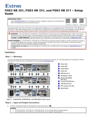
FOX3 T 321, FOX3 T 331, and FOX3 T 211 • Setup Guide
IMPORTANT NOTE:
Go to www.extron.com for the complete user guide, installation instructions, and specications
before connecting the product to the power source.
FOX3 T 321 FOX3 T 331
FOX3 T 211
This guide provides quick start instructions for an experienced installer to set up and operate the Extron FOX3 T 321, FOX3 T 331, and
FOX3 T 211 Fiber Optic transmitters.
WARNING: The FOX3 T 321, FOX3 T 331, and FOX3 T 211 outputs continuous invisible light (Class 1 rated), which may be
harmful to the eyes; use with caution. Plug the attached dust caps into the optical transceivers when the ber cable is unplugged.
CLASS 1 LASER PRODUCT, see the FOX3 T 321, FOX3 T 331, and FOX3 T 211 User Guide, at www.extron.com.
AVERTISSEMENT : Le FOX3 T 321, FOX3 T 331, et FOX3 T 211 émet une lumière invisible en continu (conforme à la classe 1)
qui peut être dangereux pour les yeux, à utiliser avec précaution. Associez les bouchons anti-poussière à l’ensemble émetteur/
récepteur optique lorsque le câble bre optique est débranché.
Produit laser de classe 1, voir le FOX3 T 321, FOX3 T 331, and FOX3 T 211 User Guide sur www.extron.com (en anglais).
Installation
Step 1 — Mounting
Turn o or disconnect all equipment power sources and mount the transmitter as required. For mounting details and considerations, see the
FOX3 T 321, FOX3 T 331, and FOX3 T 211 User Guide at www.extron.com.
Step 2 — Input and Output Connections
50-60 Hz
100-240V ~
0.7A MAX
LR
LR
RS-232
Tx Rx Tx RxG
IR
A
OUT
R
IN
INPUTS
AUDIO
RETURN
OUTPUTS
CONTROL
B
OUTIN
DISPLAYPORT
LOOP OUT
USB HID
AUDIO
FOX3 T 331
LAN
HOST
REMOTE
RS-232
Tx Rx S5VG
3D
SYNC
50-60 Hz
100-240V ~
0.7A MAX
LR
LR
RS-232
Tx Rx Tx RxG
IR
A
OUT
R
IN
INPUTS
AUDIO
RETURN
OUTPUTS
CONTROL
B
OUTIN
DISPLAYPORT
LOOP OUT
USB HID
USB 2.0
AUDIO
FOX3 T 321
LAN
HOST HOST
REMOTE
RS-232
Tx Rx S5VG
3D
SYNC
J
M
MK
KI
IC
CB
BA
A J
J L
LG
GE
ED
D
H
H
J
F
F
50-60 Hz
100-240V ~
0.7A MAX
LR
LR
RS-232
Tx Rx Tx RxG
IR
A
OUT
R
IN
INPUTS
AUDIO
RETURN
OUTPUTS
CONTROL
B
OUTIN
DISPLAYPORT
LOOP OUT
AUDIO
FOX3 T 211
LAN
REMOTE
RS-232
Tx Rx S5VG
3D
SYNC
M
M
K
KI
I
C
C
B
B
A
A J
J
L
L
D
D G
G
H
H
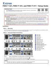
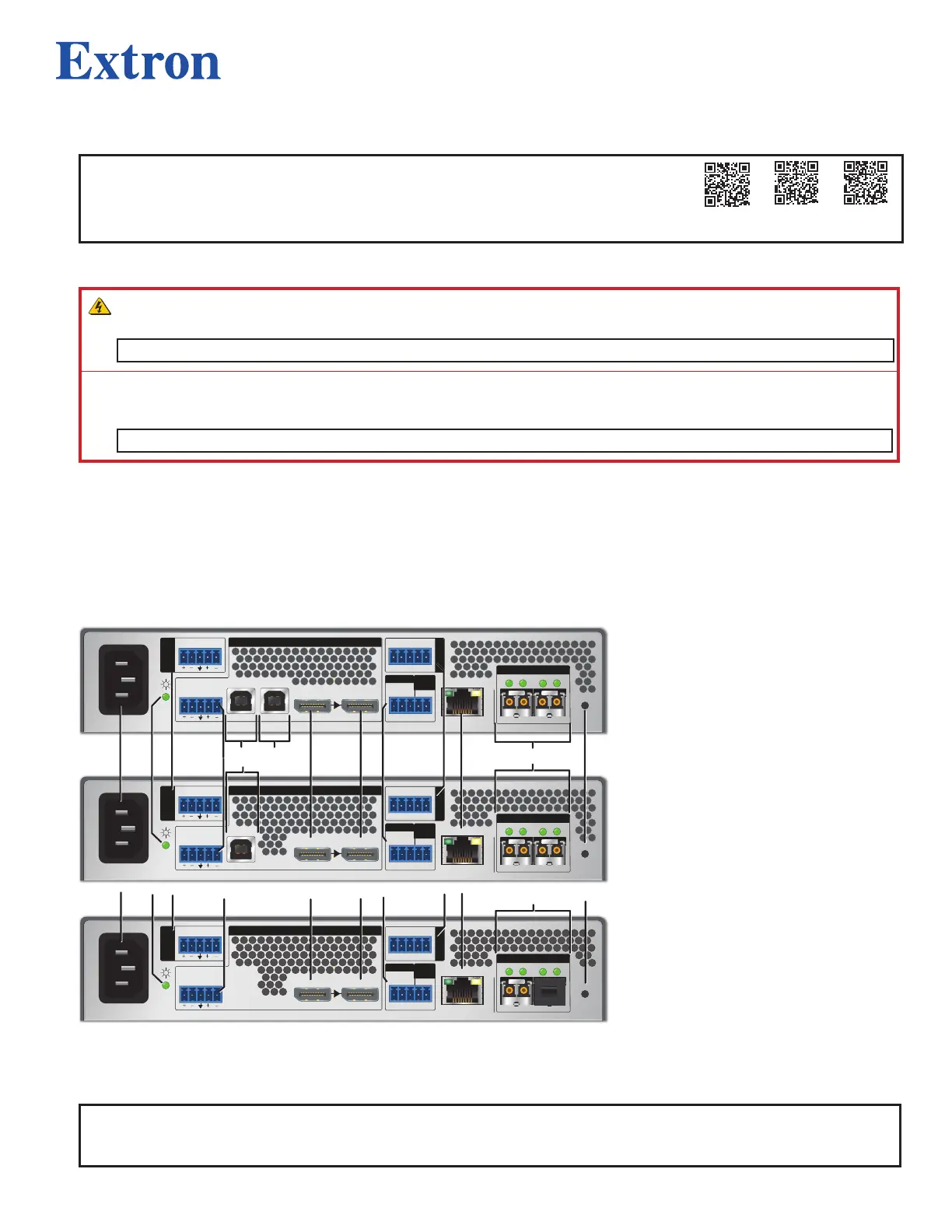
Figure 1. FOX3 T 321 (top), FOX3 T 331 (center), FOX3 T 211 (bottom) Rear Panels
A
Power Inlet
B
Power LED
C
Audio Return
D
Audio input
E
USB HID Host port
F
USB 2.0 Host ports
G
DisplayPort input
H
DisplayPort Loop Out
I
Remote RS-232/3D Sync port
J
Control RS-232/IR port
K
LAN Ethernet port
L
SFP module and LEDs
M
Reset button
a. Connect a DisplayPort video source to the DisplayPort input (see gure 1,
G
).
b. If desired, connect a DisplayPort video display to the LOOP OUT port (
H
) for a local display.
NOTES:
• The FOX3 T 321, FOX3 T 331, and FOX3 T 211 do not support HDCP-compliant devices.
• The FOX3 T 321, FOX3 T 331, and FOX3 T 211 do not support Dual-Mode DP++.
1