Festo SDAT-MHS-M160-1L-SA-E-0.3-M8 Manual

Festo Ikke kategoriseret SDAT-MHS-M160-1L-SA-E-0.3-M8

Læs gratis den danske manual til Festo SDAT-MHS-M160-1L-SA-E-0.3-M8 (4 sider) i kategorien Ikke kategoriseret. Denne vejledning er vurderet som hjælpsom af 34 personer og har en gennemsnitlig bedømmelse på 4.9 stjerner ud af 17.5 anmeldelser. Har du et spørgsmål om Festo SDAT-MHS-M160-1L-SA-E-0.3-M8, eller vil du spørge andre brugere om produktet?

Side 1/4
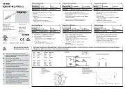
SDAT-MHS-...-SA
Position transmitter
Festo SE & Co. KG
Ruiter Straße 82
73734 Esslingen
Deutschland
+49 711 347-0
www.festo.com
Brief instruction
8163963
2021-08f
[8163965]
Translation of the original instructions
© 2022 all rights reserved to Festo SE & Co. KG
1 About this document
1.1 Applicable Documents
All available documents for the product
è www.festo.com/sp.
2 Safety
2.1 Intended use
The position transmitter is intended for contactless detection of the piston posi-
tion of magnetic proximity sensing drives and grippers.
Use the position transmitter only for suitable Festo drives and grippers.
Do not place magnetic objects in the immediate vicinity of the position trans-
mitter.
2.2 Training of qualified personnel
Work on the product may only be carried out by qualified personnel who can
evaluate the work and detect dangers. The qualified personnel have skills and
experience in dealing with electropneumatic (open-loop) control technology.
2.3 UL/CSA certification
In combination with the UL inspection mark on the product, the information in this
section must also be observed in order to comply with the certification conditions
of Underwriters Laboratories Inc. (UL) for USA and Canada.
UL approval information
Product category code NRKH, NRKH7
File number E232949
Considered standards UL 60947-1, UL 60947-5-2, CSA C22.2 No. 60947-1, CSA C22.2
No. 60947-5-2
UL mark
Ind. Cont. EQ. (Industrial Control Equipment)
2MD1
Tab. 1: UL/CSA approval information
Technical data and environmental conditions may be subject to change in order
to comply with Underwriters Laboratories Inc. (UL) certification requirements
for the USA and Canada. è 10.3 Technical data for UL/CSA certification
Only for connection to a NEC/CEC Class 2 supply.
The device shall be supplied from an isolating transformer having a secondary
listed fuse rated 1 A.
3 Additional information
Contact the regional Festo contact if you have technical problems
è www.festo.com.
Accessories and spare parts è www.festo.com/catalogue.
4 Product overview
4.1 Design
1
2
3
4
5
6
7
Fig. 1: Design of SDAT-MHS
1
Connecting cable
2
Retaining screws
3
M8 plug, rotatable
4
Red LED: status indicator
5
Green LED: ready status display
6
Yellow LED: switching status dis-
play
7
Operating key
4.2 Function
The position transmitter detects the magnetic field of the piston magnet and
continuously senses the piston movement in the sensing range.
The following output signals are available:
analogue current signal: 4 … 20 mA
programmable switching output: 24 V
IO-Link communication mode
5 Mounting
5.1 Electrical installation
WARNING
Risk of injury due to electric shock.
For the electrical power supply, use only PELV circuits in accordance with IEC
60204-1/EN 60204-1 (Protective Extra-Low Voltage, PELV).
Observe the general requirements of IEC 60204-1/EN 60204-1 for PELV circuits.
Only use voltage sources that ensure a reliable electric separation from the
mains network in accordance with IEC 60204-1/EN 60204-1.
Fig. 2: Circuit diagram
Pin Allocation Plug
1 Operating voltage +24 V DC M8x1, 4-pin
2 Analogue output 4 … 20 mA
3 0 V
4 IO-Link/switching output (C/Q line)
Tab. 2: Pin allocation of plug connection
4.
5.2 Mechanical installation
Any mounting position can be used.
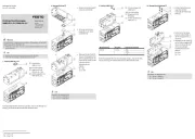
1
2
3
Fig. 3: Mechanical installation
1
Hexagon socket spanner
2
Retaining screw
3
T-slot
1. Push the position transmitter into the T-slot of the drive.
2. Move the piston to an end position of the application.
3. Push the position transmitter in the direction of the piston until the red LED
goes out.
Hand-tighten the retaining screw.
Max. tightening torque: 0.5 Nm
Tool: internal hexagon socket key (size 1.5 mm).
6 Commissioning
6.1 Switch on the position transmitter
Switch on the operating voltage.
ÄThe LEDs switch on depending on the position of the piston
è Tab. 5
LED displays in normal operation.
ÄThe device is ready for operation.
Parameter Factory setting
Switching function None
Switching logic Normally open contact (N/O)
Scaling Total sensing range
Tab. 3: Factory settings of the position transmitter
6.2 IO-Link Program output
The IO-Link function cannot be set with the operating keys on the device. All set-
tings for set-up, commissioning and parameterisation are made in the higher-level
controller of the IO-Link master.
6.3 Analogue output
The analogue output provides an output signal 4 … 20 mA.
The output signal is proportional to the path of the piston stroke in the sensing
range.
0 mm
X mm
20 mA
Fig. 4: Characteristic curve of the analogue output
X = maximum length of the sensing range
Signal Description Range1)
0 mA IO-Link operation
Error, e.g. cable break, parameter error
2 mA Piston is outside the sensing range after switching on
the operating voltage
A, C
4 mA The piston has left the sensing range in the direction of
the falling output current
A
> < 4 mA … 20 mA Piston is within the sensing range B
20 mA The piston has left the sensing range in the direction of
the rising output current
C
1) Range Fig. 2, range A and C: red LED on
Tab. 4: Output signal of the analogue output
The analogue output is switched off during active IO-Link communication. The
output current is 0 mA.
7 Operation
7.1 Magnetic direction detection and magnetic direction correction
During initial commissioning or after a reset to factory settings, the position
transmitter outputs the signals directly using the currently detected magnetic
direction.
The magnetic direction detection and, with it, the signal curve are corrected
during continuing operation in the following cases:
The position transmitter was placed in operation in a position in which it was
not possible to detect a correct magnetic direction, e.g. due to ferromagnetic
materials near the sensor or within the drive or gripper.
The position transmitter was rotated 180° in the slot after the magnetic direc-
tion was detected as stable.
Brief error signals may be detected at the sensor output if automatic correction of
the magnetic direction detection is required è 8.2 General malfunctions.
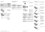
7.2 LED displays in normal operation
LED display Description
Yellow Green Red
Ready for operation:
Analogue output function or switching output operating mode.
Piston within the sensing range.
Green LED: on
Red LED: off
Ready for operation:
IO-Link operating mode.
Green LED: flashing at 1 Hz
Ready for operation:
Switching output switched.
Piston in the range of a programmed function.
Yellow LED: on
Green LED: on
Red LED: off
Status indicator:
Operating key blocked.
Green LED: flashes 3 s at
3 Hz when the operating key is
pressed


Produkt Specifikationer

Mærke: Festo
Kategori: Ikke kategoriseret
Model: SDAT-MHS-M160-1L-SA-E-0.3-M8

Har du brug for hjælp?

Hvis du har brug for hjælp til Festo SDAT-MHS-M160-1L-SA-E-0.3-M8 stil et spørgsmål nedenfor, og andre brugere vil svare dig