Festo VABA-S6-1-PT Manual

Festo Ikke kategoriseret VABA-S6-1-PT

Læs gratis den danske manual til Festo VABA-S6-1-PT (2 sider) i kategorien Ikke kategoriseret. Denne vejledning er vurderet som hjælpsom af 10 personer og har en gennemsnitlig bedømmelse på 4.8 stjerner ud af 5.5 anmeldelser. Har du et spørgsmål om Festo VABA-S6-1-PT, eller vil du spørge andre brugere om produktet?

Side 1/2
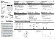
VABA-S6-1-PT
Electrical interface
Festo SE & Co. KG
Ruiter Stre 82
73734 Esslingen
Deutschland
+49 711 347-0
www.festo.com
Operating instructions
8162836
2021-11
[8162838]
Translation of the original instructions
© 2021 all rights reserved to Festo SE & Co. KG
IO-Link® is a registered trademark of its respective trademark holder in certain
countries.
1 Applicable documents
All available documents for the product
è www.festo.com/sp.
Document Product Contents
Assembly instructions VTSA, VTSA-F
Description VTSA, VTSA-F Pneumatics description
Description Bus node CTEU-... Assembly, Installation, Opera-
tion
Tab. 1: Applicable documents
2 Safety
2.1 Safety instructions
Before working on the product, switch off the power supply and secure it
against being switched on again.
Before working on the product, switch off the compressed air supply and lock it
to prevent it from being switched on again.
Exhaust system parts with stored compressed air.
Only use the product if it is in perfect technical condition.
Only use the product in its original condition without unauthorised modifica-
tions.
Only the conversions or modifications described in the documentation are
permitted. Conversions can change the function of the valve terminal. Check
the conversion target with the configurator before carrying out conversions
è www.festo.com.
Take into account the ambient conditions at the location of use.
Observe the handling specifications for electrostatically sensitive devices.
The product may generate high frequency interference, which may require
interference suppression measures in residential areas.
Store the product in a cool, dry environment protected from UV and corrosion.
Keep storage times short.
2.2 Intended use
The electrical interface VABA-S6-1-PT with IO-Link/I-Port interface is suitable for
retrofit in valve terminals type VTSA-MP (-NPT) and VTSA-F-MP (-NPT).
The product is used to control pneumatic actuators and is installed in machines
and automation systems.
2.3 Training of qualified personnel
Work on the product may only be carried out by qualified personnel who can
evaluate the work and detect dangers. The qualified personnel have skills and
experience in dealing with electrical (open-loop) control technology.
3 Additional information
Contact the regional Festo contact if you have technical problems
è www.festo.com.
Accessories and spare parts è www.festo.com/catalogue.
4 Design
1
23
Fig. 1: VABA-S6-1-PT connections
1
Status LED X1
2
IO-Link/I-Port connection
3
Earth terminal
5 Assembly
The product is suitable for retrofit in existing valve terminals with multi-pin con-
nection type VTSA-MP (-NPT) and VTSA-F-MP (-NPT).
The IO-Link/I-Port module can be fitted with the ASLR-C-E4 inscription label.
When retrofitting the VABA-S6-1-PT in existing valve terminals, note the following
points:
The installation changes the function of the valve terminal. Before instal-
ling the new configuration, check its validity online with the configurator
è www.festo.com.
Retrofit of the VABA-S6-1-PT invalidates the current ATEX approval of the valve
terminal.
Proceed as follows to install the product:
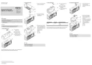
1. Remove the multi-pin node of the valve terminal in accordance with the
description of the valve terminal è 1 Applicable documents.
2. Install the electrical interface VABA-S6-1-PT with IO-Link/I-Port interface in
accordance with the description of the valve terminal
è 1 Applicable docu-
ments.
6 Electrical installation
WARNING
Risk of injury due to electric shock.
For the electric power supply, use only PELV circuits that ensure a reliable
electric disconnection from the mains network.
Observe IEC 60204-1/EN 60204-1.
6.1 Power supply
The operating voltage is supplied via the IO-Link master or the CTEU bus node.
The load voltage supply is via the IO-Link master port class B or the CTEU bus
node. When using an IO-Link master port class A, the load voltage supply must be
separate. Separate fuses are required for operating and load voltage.
6.2 IO-Link interface
The valve terminal can be connected as follows via the IO-Link/I-Port interface:
directly to the fieldbus by mounting a CTEU bus node on the valve terminal
decentralised to an external IO-Link master
Electrical connection:
Plug, 5-pin, M12, A-coded
Pin allocation IO-Link/I-Port interface
Connection Pin Allocation Function
1 24 VEL/SEN(PS) Operating voltage for electronics
2 24 VVAL/OUT(PL) Operating voltage for load
3 0 VEL/SEN(PS) Operating voltage for electronics
4 C/Q Data communication
5 0 VVAL/OUT (PL) Operating voltage for load
Housing, FE Functional earth (optional)
Tab. 2: Pin allocation IO-Link/I-Port interface
Device description file IODD
If the valve terminal is operated as a IO-Link device, download the corresponding
device description file è www.festo.com/sp.
6.3 Earthing
Connect the valve terminal to the functional earth via the earth terminal è 4
Design.
7 Operation
7.1 LED display X1, IO-Link/I-Port communication
LED X1 Meaning
green light Data communication faulty.
flashing
green
Normal operating status
flashing red Device error
red light 24 V load voltage supply faulty.
Data communication may be faulty.
off 24 V operating voltage supply disconnected or undervoltage
Tab. 3: LED X1
7.2 Address assignment
A maximum of 32 solenoid coils can be actuated.
Valve position 0 is located on the left-hand side.
Address assignment is in ascending order without gaps, from left to right.
Address assignment does not depend on whether the module is equipped with
blanking plates.
A valve position always occupies two addresses. The following allocation
applies here:
Solenoid coil for switching position 14: low-value address
Solenoid coil for switching position 12: higher-value address
1 2
4
3
Fig. 2: Example of address assignment
with 12 valve positions
1
Example of valve position 0:
Solenoid coil SP1 (address 0)
Solenoid coil SP2 (address 1)
2
Blanking plate
3
Addresses of the solenoid coils 14
4
Addresses of the solenoid coils 12
8 Malfunctions
Error code Type Malfunction and error handling
MSB LSB
50h 00h Error Device error
Switch the device off and on again; if the
error persists, the device is defective.
51h 12h Warning Error in the load voltage supply
Check the load voltage supply
Tab. 4: Error Diagnostics
9 Technical data
Environmental conditions
Ambient temperature [°C] –5 … +50
Storage temperature [°C] –20 … +60
Degree of protection IP651)
1) Valve terminal completely mounted, plug connected.
Tab. 5: Environmental conditions
Electrical Characteristics
Power supply
Operating voltage for electronics [V DC] 24 ± 25 %
Operating voltage for load [V DC] 24 ± 10 %
Current consumption
Intrinsic current consumption of elec-
tronics
[mA] 30
Intrinsic current consumption of load [mA] Depending on the valves installed in the valve
terminal. See Description VTSA/VTSA-F
è 1
Applicable documents
IO-Link interface
Specification V1.1 (V1.0 compatible)
Port class B (type B)
Baud rate Com 2 (38.4 kBit)
Output data 4 bytes (up to 16 valves)
Tab. 6: Electrical Characteristics
Tightening torques
Electrical interface [Nm] 0.7 ± 20 %
Earthing screw [Nm] 2 ± 10 %
Linking [Nm] See Description VTSA/VTSA-F
è 1 Applicable
documents
Tab. 7: Tightening torques


Produkt Specifikationer

Mærke: Festo
Kategori: Ikke kategoriseret
Model: VABA-S6-1-PT

Har du brug for hjælp?

Hvis du har brug for hjælp til Festo VABA-S6-1-PT stil et spørgsmål nedenfor, og andre brugere vil svare dig