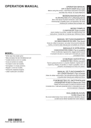
Fujitsu Airstage AJH072GALDH Manual

Fujitsu Aircondition Airstage AJH072GALDH

Læs gratis den danske manual til Fujitsu Airstage AJH072GALDH (23 sider) i kategorien Aircondition. Denne vejledning er vurderet som hjælpsom af 23 personer og har en gennemsnitlig bedømmelse på 4.6 stjerner ud af 12 anmeldelser. Har du et spørgsmål om Fujitsu Airstage AJH072GALDH, eller vil du spørge andre brugere om produktet?

Side 1/23
English
PART No. 9378945692-02
Deutsch
TM
FrançaisEspañolItalianoΕλληνικάPortuguêsРусскийTürkçe
AJ*072GALDH
AJ*090GALDH
AJ*108GALDH
AJ*126GALDH
AJ*144GALDH
OUTDOOR UNIT
AUßENGERÄT
UNITÉ EXTÉRIEURE
UNIDAD EXTERIOR
UNITÀ ESTERNA
ǼȄȍȉǼȇǿȀdzȂȅȃDZǻǹ
UNIDADE EXTERIOR
ȼɇȿɒɇɂɃɆɈȾɍɅɖ
DIùh1øTE
INSTALLATION MANUAL
For authorized service personnel only.
INSTALLATIONSANLEITUNG
Nur für autorisiertes Fachpersonal.
MANUEL DINSTALLATION
MANUAL DE INSTALACIÓN
Pour le personnel agréé uniquement.
Únicamente para personal de servicio autorizado.
MANUALE DI INSTALLAZIONE
A uso esclusivo del personale tecnico autorizzato.
ƧƥƸƧƫƳƫƦƫƱƧƥƬƣƵƣƴƵƣƴƩƴ
ȂȩȞȠȖȚĮİȟȠȣıȚȠįȠIJȘȝȑȞȠIJİȤȞȚțȩʌȡȠıȦʌȚțȩ.
MANUAL DE INSTALÃO
Apenas para técnicos autorizados.
ǾȁǸǼǰǼDzǿȀǰǼǽǼȁǿȀǮǻǼǰǸdz
Ɍɨɥɶɤɨ ɞɥɹ ɚɜɬɨɪɢɡɨɜɚɧɧɨɝɨ ɨɛɫɥɭɠɢɜɚɸɳɟɝɨɩɟɪɫɨɧɚɥɚ.
YalnÕ]ca yetkili servis personeli için.
MONTAJ KILAVUZU
En-1
INSTALLATION MANUAL
PART No. 9378945692-02
VRF system outdoor unit
Contents
1. SAFETY PRECAUTIONS ........................................................................................... 1
2. ABOUT THIS PRODUCT ............................................................................................ 2
2.1. Precautions for using R410A refrigerant .......................................................... 2
2.2. Special tools for R410A .................................................................................... 2
2.3. Accessories ..................................................................................................... 2
2.4. Combinations ................................................................................................... 2
2.5. Optional parts................................................................................................... 3
3. INSTALLATION WORK ............................................................................................... 3
3.1. Selecting an installation location ...................................................................... 3
3.2. Drain processing .............................................................................................. 3
3.3. Clearance requirement .................................................................................... 3
3.4. Transporting the unit ........................................................................................ 5
3.5. Installing the unit .............................................................................................. 5
4. SYSTEM CONFIGURATION ...................................................................................... 6
4.1. System con guration ....................................................................................... 6
4.2. Pipe selection................................................................................................... 7
4.3. Protection of pipes ........................................................................................... 8
5. PIPE INSTALLATION .................................................................................................. 8
5.1. Brazing ............................................................................................................. 8
5.2. Indoor unit pipe connections ............................................................................ 8
5.3. Opening the knockout hole .............................................................................. 8
5.4. Pipe connection ............................................................................................... 9
5.5. Multiple connections ........................................................................................ 9
6. ELECTRICAL WIRING ...............................................................................................11
6.1. The precautions of electrical wiring .................................................................11
6.2. Wiring method .................................................................................................11
6.3. Knockout hole ................................................................................................ 12
6.4. Selecting power supply cable and breaker .................................................... 12
6.5. Transmission line ........................................................................................... 12
6.6. Wiring procedure............................................................................................ 13
6.7. External input and external output ................................................................. 14
7. FIELD SETTING ....................................................................................................... 15
7.1. Field setting switches ..................................................................................... 15
7.2. DIP switch setting .......................................................................................... 15
7.3. Rotary switch setting ...................................................................................... 16
7.4. Push button setting ........................................................................................ 16
7.5. Address setting for signal ampli ers .............................................................. 18
7.6. Indoor unit address setting ............................................................................. 18
7.7. RB unit address setting .................................................................................. 18
7.8. Resistance measurement of transmission cable
(Measure with breaker OFF) .......................................................................... 19
8. PIPE INSTALLATION II ............................................................................................. 19
8.1. Sealing test .................................................................................................... 19
8.2. Vacuum process ............................................................................................ 19
8.3. Additional charging ........................................................................................ 20
8.4. Installing insulation ......................................................................................... 21
9. TEST RUN ................................................................................................................ 21
9.1. Pre-check for test run..................................................................................... 21
9.2. Test run method ............................................................................................. 21
9.3. Checklist ........................................................................................................ 21
10. LED STATUS ............................................................................................................ 22
10.1. Normal operation codes ................................................................................. 22
10.2. Error codes .................................................................................................... 22
11. INFORMATION ......................................................................................................... 22
1. SAFETY PRECAUTIONS
• Be sure to read this Installation manual thoroughly before installation.
• The warnings and precautions indicated in this Installation manual contain important
information pertaining to your safety. Be sure to observe them.
• After installing the unit, perform a test run to make sure the unit operates normally. Then,
explain to the customer how to operate and maintain the unit.
• Please pass this Installation manual together with the Operating manual to the customer.
Please ask the customer to keep the Operating manual and Installation manual at hand
for future reference during the moving or repair of the main unit.
WARNING This mark indicates procedures which, if improperly per-
formed, might lead to the death or serious injury of the user.
For installation purposes, be sure to use the parts supplied by the manufacturer or other
prescribed parts.
Using non-specified parts will cause serious accidents such as falling unit, refrigerant
leakage, water leakage, electric shock, and fire.
To install a unit that uses the R410A refrigerant, use dedicated tools and piping
materials that have been manufactured specifically for R410A use.
Because the pressure of the R410A refrigerant is approximately 1.6 times higher than
the R22, failure to use dedicated piping material or improper installation can cause
rupture or injury.
It will also cause serious accidents such as refrigerant leakage, water leakage, electric
shock, and fire.
Do not use this equipment with air or any other unspecified refrigerant in the refrigerant
lines.
Excess pressure can cause a rupture.
Be sure to install the unit as prescribed, so that it can withstand earthquakes and
typhoons or other strong winds.
Improper installation can cause the unit to topple or fall, or other accidents
.
Ensure that the outdoor unit is securely installed at a place that can withstand the
weight of the unit.
Improper installation will cause injuries caused by falling unit.
If there is a refrigerant leakage, make sure that it does not exceed the concentration
limit.
If a refrigerant leakage exceeds the concentration limit, it can lead to accidents such as
oxygen starvation.
If a refrigerant leakage occurs during operation, immediately vacate the premises and
thoroughly ventilate the area.
If the refrigerant is exposed to fire, it will create a hazardous gas.
Electrical work must be performed in accordance with this Installation manual by a
person certified under the national or regional regulations. Be sure to use a dedicated
circuit for the unit.
An insufficient power supply circuit or improperly performed electrical work can cause
serious accidents such as electric shock or fire.
For wiring, use the prescribed type of cables, connect them securely, making sure that
there are no external forces of the cables applied to the terminal connections.
Improperly connected or secured cables can cause serious accidents such as overheat-
ing the terminals, electric shock, or fire.
Do not turn ON the power until all work has been completed.
Turning ON the power before the work is completed can cause serious accidents such
as electric shock or fire.
After the installation, make sure there is no refrigerant leakage.
If the refrigerant leaks into the room and becomes exposed to a source of fire such as a
fan heater, stove, or burner, it will create a hazardous gas.
Use a wall hole pipe. Otherwise, it may cause a short circuit.
Do not place the outdoor unit near the handrail of the balcony.
Children may climb onto the outdoor unit, lean over the handrail and fall over.
Use only a specified power cable. Poor connection, poor insulation, and exceeding the
allowable current will lead to electric shock and fire
.
Attach the connecting cables securely to the terminal. Or secure it firmly with a "wiring
suppressor".
Loose connection will lead to malfunction, electric shock, and fire.
Install a breaker to cut off all AC main current at the same time.
If you do not install a breaker, it may cause electric shock and fire.
During installation, make sure that the refrigerant pipe is attached firmly before you run
the compressor.
Do not operate the compressor under the condition of refrigerant piping not attached
properly with 2-way or 3-way valve open. This may cause abnormal pressure in the
refrigeration cycle that leads to rupture and even injury.
During the pump-down operation, make sure that the compressor is turned off before
you remove the refrigerant piping. Do not remove the connection pipe while the
compressor is in operation with 2-way or 3-way valve open. This may cause abnormal
pressure in the refrigeration cycle that leads to breakage and even injury.
If there is a possibility of touching the fan during maintenance, make sure to turn OFF
the power before implementing the maintenance. Even if operations are suspended,
the fan of outdoor unit sometimes rotates, so if the fan rotates suddenly while in contact
with you may cause serious injury.
[Original instructions]
En-3
Space saving combination
Combination (HP) 8 10 12 14 16 18 20 22 24 26 28
Outdoor Unit 1 (HP) 8 10 12 14 16 10 10 12 12 16 16
Outdoor Unit 2 (HP) - - - - - 8 10 10 12 10 12
Outdoor Unit 3 (HP) -----------
Maximum Connectable Indoor Unit 17 21 26 30 34 39 43 47 52 56 60
Combination (HP) 30 32 34 36 38 40 42 44 46 48
Outdoor Unit 1 (HP) 16 16 12 12 16 16 16 16 16 16
Outdoor Unit 2 (HP) 14 16 12 12 12 12 16 16 16 16
Outdoor Unit 3 (HP) - - 10 12 10 12 10 12 14 16
Maximum Connectable Indoor Unit 64 64 64 64 64 64 64 64 64 64
When connecting outdoor units, install the outdoor unit with the largest nominal system
capacity nearest to the refrigerant pipe and indoor unit, followed by those with lesser
nominal system capacities. (Outdoor unit 1 Outdoor unit 2 Outdoor unit 3)≥ ≥
Energy-saving combination
Combination (HP) 8 10 12 14 16 18 20 22 24 26 28
Outdoor Unit 1 (HP) - - - - 8 - - 14 8 10 10
Outdoor Unit 2 (HP) - - - - 8 - - 8 8 8 10
Outdoor Unit 3 (HP) - - - - - - - - 8 8 8
Maximum Connectable Indoor Unit * * * * 34 * * 47 52 56 60
Combination (HP) 30 32 34 36 38 40 42 44 46 48
Outdoor Unit 1 (HP) 10 14 14 14 14 16 14 16 - -
Outdoor Unit 2 (HP) 10 10 10 14 14 14 14 14 - -
Outdoor Unit 3 (HP) 10 8 10 8 10 10 14 14 - -
Maximum Connectable Indoor Unit 64 64 64 64 64 64 64 64 * *
* Means that the energy-saving combination is unavailable.
When connecting outdoor units, install the outdoor unit with the largest nominal system
capacity nearest to the refrigerant pipe and indoor unit, followed by those with lesser
nominal system capacities. (Outdoor unit 1 Outdoor unit 2 Outdoor unit 3)≥ ≥
2.5. Optional parts
CAUTION
The following parts are optional parts specific to R410A refrigerant.
Do not use parts other than those listed below.
2.5.1 RB unit
RB unit Total cooling capacity of indoor unit [kW]
UTP-RX01AH 8.0 or less
UTP-RX01BH 18.0 or less
UTP-RX01CH 28.0 or less
UTP-RX04BH 18.0 or less (for 1 branch)
56.0 or less (Sum total of 4 branches) (*1)
UTP-RX08AH 8.0 or less (for 1 branch)
72.0 or less (Sum total of 8 branches)
UTP-RX12AH 8.0 or less (for 1 branch)
95.0 or less (Sum total of 12 branches)
*1: In case of 2
RB units con-
nected in series
(total 8 branches),
maximum capacity
of connectable in-
door units is up to
56.0 kW.
2.5.2 Outdoor unit branch kit
Model Total cooling capacity of indoor unit [kW]
UTP-DX567A ALL
2.5.3 Separation tube
Model Total cooling capacity of
indoor unit [kW]
for 2 pipes for 3 pipes
UTP-AX054A 19.6 or less
UTP-AX090A UTP-BX090A 28.0 or less
UTP-AX180A UTP-BX180A 28.1 to 56.0
UTP-AX567A UTP-BX567A 56.1 or more
2.5.4 Header
Model: for 2 pipes Model: for 3 pipes Total cooling capacity
of indoor unit [kW]
3-6
branches
3-8
branches
3-6
branches
3-8
branches
UTR-H0906L UTR-H0908L UTP-J0906A UTP-J0908A 28.0 or less
UTR-H1806L UTR-H1808L UTP-J1806A UTP-J1808A 28.1 to 56.0
2.5.5 External connect kit
Model Usage
UTY-XWZXZ6
For External input (CN131, CN133, CN134)
For External output
(Error status / CN136) (Operation status / CN137)
UTY-XWZXZF For External input (CN135)
UTY-XWZXZ9 For External output (Base heater / CN115)
3. INSTALLATION WORK
Please obtain the approval of the customer when selecting the location of installation and
installing the main unit.
3.1. Selecting an installation location
WARNING
Install the unit in a location that can withstand its weight, and where it will not topple or
fall.
Calculate the proper refrigerant concentration if you will be installing it in an enclosed
location.
Total amount of replenished refrigerant
in refrigerant facility (kg)
Refrigerant concentration (kg/m³)
(0.42 kg/m³)
Capacity of smallest room where unit
is installed (m³)
If the results of the calculation exceed the concentration limit, increase the room surface
area or install a ventilation duct.
CAUTION
Select an installation location by observing the following precautions:
Install the unit level. (Within 3 degrees)
Install this unit in a location with good ventilation.
If the unit must be installed in an area within easy reach of the general public, install as
necessary a protective fence or the like to prevent their access.
Install the unit in an area that would not inconvenience your neighbors, as they could be
affected by the airflow coming out from the outlet, noise, or vibration.
If it must be installed in proximity to your neighbors, be sure to obtain their approval.
If the unit is installed in a cold region that is affected by snow accumulation, snow fall, or
freezing, take appropriate measures to protect it from those elements.
To ensure a stable operation, install inlet and outlet ducts.
Install the unit in an area that would not cause problems even if the drain water is
discharged from the unit. Otherwise, provide drainage that would not affect people or
objects.
Install the unit in an area that has no heat sources, vapors, or the risk of the leakage of
flammable gas in the vicinity.
Install the unit in an area that is away from the exhaust or vent ports that discharge
vapor, soot, dust, or debris.
Install the indoor unit, outdoor unit, power supply cable, transmission cable and remote
control cable at least 1 meter away from a television or radio.
The purpose of this is to prevent TV reception interference or radio noise. (Even if they
are installed more than 1 meter apart, you could still receive noise under some signal
conditions.)
Keep the length of the piping of the indoor and outdoor units within the allowable range.
For maintenance purposes, do not bury the piping.
3.2. Drain processing
• The drain water is discharged from the bottom of the equipment. Construct a drain ditch
around the base and discharge the drain water properly.
• When installing on a roof, perform floor waterproofing properly.
Drain processing:
• The drain water from the base of the outdoor unit
may generate during operations.
Perform drain processing, as necessary.
• When you want to prevent the drain water from leak-
ing at the perimeter, construct a ditch for the drain
water as shown in the figure.
• Provide a central drain pan, as necessary.
Outdoor unit
10 mm
or more
50 mm
or more
3.3. Clearance requirement
CAUTION
When installing the outdoor unit, pay attention to the following items.
Provide sufficient installation space, such as transportation route, maintenance space,
ventilation space, refrigerant piping space, and passageways.
Pay attention to the specifications of the installation space as shown in the figure. If
the unit is not installed according to specifications, it may cause short circuit or poor
performance. The unit may be prone to lapse into non-operation due to high pressure
protection.
Do not place obstructions in the air flow outlet direction. If there is an obstruction in the
outlet direction, install an outlet duct.
When there is a wall in front of the unit, provide a space of 500 mm or more as
maintenance space.
When there is a wall at the left side of the unit, provide a space of 30 mm or more as
maintenance space.
An outdoor temperature of 35 degrees in air-conditioned operation is assumed for the
installation space in this item. If the outdoor temperature exceeds 35 degrees and
the outdoor unit is operating at a load exceeding its rated ability, provide a larger inlet
space.
En-4
CAUTION
If you are installing more outdoor units than indicated here, please ensure sufficient
space or consult your distributing agent as it may affect the performance due to short
circuit and other problems.
3.3.1 When install nearby limited height wall
(1) Single and multiple installations
• There are no restrictions on the height of the side wall.
• Provide installation spaces L1 and L2 in accordance with the table below according to the
wall height (front side, rear side) conditions.
• Provide installation spaces other
than L1 and L2 in accordance with
the conditions shown in the figure
below.
• Ventilation resistance can be
ignorable when the distance from
a wall or product, etc. is larger
than 2 m.
Wall height condition
[mm]
Necessary
installation space
[mm]
When H1 is 1,500 or less L1 500
When H1 is 1,500 or more L1 500 + p5-h1 ÷ 2
When H2 is 500 or less L2 100
When H2 is 500 or more L2 100 + p5-h2 ÷ 2
Single installation
500
L1 L2
H1
h1
H2
h2
Unit: mm
10 or
more
30 or
more
1,500
Multiple installations
500
L1 L2
H1
h1
H2
h2
Unit: mm
30 or
more
20 or
more
20 or
more
20 or
more
1,500
(2) Concentrated installation
• Provide installation spaces L3,
L4, and L5 in accordance with
the table below according to
the wall height (front side, rear
side) conditions.
• Provide installation spaces
other than L3, L4, and L5 in
accordance with the conditions
shown in the figure below.
• Ventilation resistance can be
ignorable when the distance
from a wall or product, etc. is
larger than 2 m.
Wall height condition [mm] Necessary installa-
tion space [mm]
When H3 is 1500 or less L3 500
When H3 is 1500 or more L3 500 + p5-h3 ÷ 2
When H4 is 500 or less L4 200
When H4 is 500 or more L4 200 + p5-h4 ÷ 2
When H5 is 500 or less L5 200
When H5 is 500 or more L5 200 + p5-h5 ÷ 2
500
L3 L2
H3
h3
H4
h4
L5 L5
500
H5
h5
500
H5
h5
Unit: mm
20 or
more
20 or
more
800 or
more
800 or
more
1,500
L5 L5
500
L3 L2
H3
h3
H4
h4
500
H5
h5
500
H5
h5
Unit: mm
20 or
more
20 or
more
1,000
or more
500 or
more
1,500
3.3.2 When install near unlimited height wall
(1) Single and multiple installations
• There are no restrictions on the height of the wall.
• The wall (without height restrictions) must not exist on the both sides (left / right) of
outdoor unit. Also, must not exist on the both sides (front / rear) of outdoor unit.
• Provide installation spaces other than L6 in accordance with the conditions shown in the
figure below.
• Ventilation resistance can be ignorable when the distance from a wall or product, etc. is
larger than 2 m.
When installing with the
rear of the outdoor unit
facing the wall side
Condition Necessary installation
space
When B 400 (mm) L6 200 (mm) ≥ ≥
When 20 B < 400 (mm)L6 200 + (400 - B) × 3
(mm)
Single installation
Unit: mm
200 or
more
100 or
more
Multiple installations
BB
L6
Unit: mm
200 or
more
Example :
When B is made 200 mm
L6 200 + (400-200) × 3 = 800 mm
Unit: mm
200 or
more
200 200
800 or
more
En-5
When installing with the FRONT of the outdoor unit facing the wall side
Unit: mm
200 or
more
500 or
more
Unit: mm
200 or
more
20 or
more
20 or
more
500 or
more
(2) Concentrated Installation
The wall (without height restrictions) must not exist on the both sides (left / right) of outdoor
unit. Also, must not exist on the both sides (front / rear) of outdoor unit.
• Ventilation resistance can be ignorable when the distance from a wall or product, etc. is
larger than 2 m.
Unit: mm
1,000 or
more
400 or
more
400 or
more
800 or
more
800 or
more
400 or
more
Unit: mm
1,000 or
more
1,000 or
more
400 or
more
400 or
more
500 or
more
400 or
more
3.3.3 When there are obstacles above the product
When there are obstacles above the product, keep the
minimum installation height as shown in the figure and
install the outlet duct.
When installing the outlet duct, you must set the high
static pressure mode with the push-button switch.
(Similar when installing anti-snow hood)
500 mm
or more
Outlet duct
Setting high static pressure mode
Follow the instructions in the table below to set the high
static pressure mode.
Condition High static pressure mode
setting (*2)
Static Pressure (SP):
0 SP 30 (Pa) (*1)≤ ≤ Set to High static pressure 1
Static Pressure (SP):
30 < SP 80 (Pa) (*1)Set to High static pressure 2
*1: Static pressure is the airflow resistance that includes
the discharge duct resistance & the other additional
resistance like discharge grill and so on.
*2: Refer to the section on Push button setting in “7.
FIELD SETTING”.
3.4. Transporting the unit
Hoisting method
• When hanging the outdoor unit and conveying it to installation location, hang the unit
with rope by passing through the 4 opening holes on bottom of front and rear side as
shown in figure.
Use 2 ropes at least 8 m long. If
used shorter length, it may cause
to damage to the unit
.
• Use the sufficiently strong rope
to bear the unit’s weight.
• Place the protective board or
filler cloth at the place where
the cabinet may come into
contact with rope to prevent from
damages. Without using them,
cabinet may cause to damage
or deform.
• During the hanging unit, make
sure to keep the unit level to
prevent from falling.
• To prevent the unit swing
accident or falling down of the
unit, do not apply any impact to
the unit when it is hanging.
Opening
space
Protective
boards
Product mass (kg)
AJ*072GALDH 262
AJ*090GALDH 262
AJ*108GALDH 262
AJ*126GALDH 286
AJ*144GALDH 286
Lifting by forklift
• When using the forklift to lift
the unit, pass the forklift arms
through the opening space as
shown in below.
Fork (Forklift) Delivery pallet
Fork (forklift) or
Fork (Manual
forklift)
<Front> <Side>
Front: Bottom of the wooden
delivery pallet.
Side: Space between pallet
and cabinet.
(Enable to remove the pallet
from cabinet.)
• Be careful not to damaged.
Lifting by forklift (Manual forklift: hand-fork)
• When using the manual forklift to lift the unit, pass the forklift arms through to the
opening space between pallet and cabinet from side.
3.5. Installing the unit
• Install the unit level. (within 3 degrees).
• Install 4 or more anchor bolts at the 8 locations indicated by arrows (Fig. A).
• Place the left and right anchor bolts at a distance further away than the dimensions of A
in the Table A.
(Excluding the case where anchor bolts are installed at 8 places.)
Fig. A
732
765
80 80
160160
B
A
Holes:
12 × 17
(8 places)
Bottom view
(Unit: mm)
Table. A
Model A B
AJ*072GALDH 610 930
AJ*090GALDH 610 930
AJ*108GALDH 610 930
AJ*126GALDH 920 1240
AJ*144GALDH 920 1240
En-6
• To minimize vibration, do not install the outdoor unit directly on the ground.
Instead, install it on top of a firm platform (such as concrete block). (Fig. B)
• The foundation base should be able to support the product and the foot width of the
product should be more than 46.5 mm.
• Depending on the installation condition, vibration during the operation of the unit may
cause noise and vibration.
Install vibration-proofing materials (such as rubber pads).
• Consider the removal space of the connection piping when installing the foundation.
• Secure the equipment firmly with anchor bolts, washers, and nuts.
Fig. B
Bolt (M10)
*Do not use a four-corner support foundation.
GOODPROHIBITED GOOD
Fig. C
When installing piping from the
bottom of the outdoor units, the
required space under the outdoor
unit 200 mm.
* Install the branch kit horizontally.
200 mm
or more
4. SYSTEM CONFIGURATION
For detailed information, refer to the Design and Technical Manual.
4.1. System con guration
CAUTION
• When connecting multiple outdoor units, set the nearest outdoor unit to the indoor unit
on the refrigerant pipe as the primary unit.
• When connecting multiple outdoor units, install the outdoor unit with the largest
nominal system capacity nearest to the indoor unit on the refrigerant pipe, followed by
those with less nominal system capacities.
[Capacity: Primary Subordinate]
• Always keep to the limit on the total amount of refrigerant. Exceeding the limit on the
total amount of refrigerant when charging will lead to malfunction.
4.1.1 In case of 1 outdoor unit connected
(Primary)
Outdoor unit
RB unit
Indoor unit
(*1: Cooling only)
Allowable pipe length (actual pipe length)
Between primary outdoor unit and the farthest indoor
unit 165 m or less a + f
a + p
Between the first separation tube and the farthest
indoor unit 90 m or less f, p
(Farthest indoor unit) - (Closest indoor unit) 60 m or less f(p) - g(q)
Total pipe length 700 m or less Total
Allowable height difference
Between outdoor unit and indoor unit (When indoor
unit is installed below) 50 m or less
H1
Between outdoor unit and indoor unit (When outdoor
unit is installed below) 40 m or less
Between indoor units 15 m or less H2, H3
Between RB unit and indoor unit 5 m or less H4
Between RB units 15 m or less H5
• Total refrigerant amount: 35 kg or less
4.1.2 In case of 2 outdoor units connected
(Subordinate)
(Primary)
(*1: Cooling only)
Outdoor unit
RB unit
Indoor unit
Allowable pip length (actual pipe length)
Between primary outdoor unit and the farthest indoor
unit 165 m or less a + e + f
a + e + p
Between the first separation tube and the farthest
indoor unit 90 m or less f, p
(Farthest indoor unit) - (Closest indoor unit) 60 m or less f(p) - g(q)
Total pipe length 1000 m or less Total
Between outdoor unit and outdoor unit branch kit 3 m or less a, b
Allowable height difference
Between outdoor unit and indoor unit (When indoor
unit is installed below) 50 m or less
H1
Between outdoor unit and indoor unit (When outdoor
unit is installed below) 40 m or less
Between indoor units 15 m or less H2, H3
Between outdoor units 0.5 m or less H4
Between RB unit and indoor unit 5 m or less H5
Between RB units 15 m or less H6
• Total refrigerant amount: 70 kg or less
• Outdoor unit capacity: Primary Subordinate
4.1.3 In the case of 3 outdoor units connected
(Subordinate 2)
(Subordinate 1)
(Primary)
(*1: Cooling only)
Outdoor unit
RB unit
Indoor unit
Allowable pip length (actual pipe length)
Between primary outdoor unit and the
farthest indoor unit 165 m or less a + e + f
a + e + p
Between the first separation tube and the farthest
indoor unit 90 m or less f, p
(Farthest indoor unit) - (Closest indoor unit) 60 m or less f(p) - g(q)
Total pipe length 1000 m or less Total
Between outdoor unit and outdoor unit branch kit 3 m or less a, b, c
Between the farthest outdoor unit and the first out-
door unit branch kit 12 m or less b + d
c + d
En-7
Allowable height difference
Between outdoor unit and indoor unit (When indoor
unit is installed below) 50 m or less
H1
Between outdoor unit and indoor unit (When outdoor
unit is installed below) 40 m or less
Between indoor units 15 m or less H2, H3
Between outdoor units 0.5 m or less H4
Between RB unit and indoor unit 5 m or less H5
Between RB units 15 m or less H6
• Total refrigerant amount: 105 kg or less
• Outdoor unit capacity: Primary Subordinate 1 Subordinate 2≥ ≥
NOTE:
• If the outdoor temperature during cooling operation is expected to be
–5°C or less, outdoor unit must be installed lower than 5 m or less from the indoor unit.
• Please refer to “8.3.2 Checking total amount of refrigerant and calculating the amount
of refrigerant charge to be added” for the total amount of refrigerant.
4.2. Pipe selection
CAUTION
This unit is designed specifically for use with the R410A refrigerant. Pipes for R407C or
R22 may not be used with this unit. Do not use existing pipes. Improper pipe selection
will degrade performance.
O.U.
-3
O.U.
-2
O.U.
-1
I.U.
RB RB
I.U. I.U.
I.U. I.U. I.U. I.U. I.U.
Outdoor unit branch kit (Optional)
Separation tube (Optional)
RB (multi type)
(single
type)
Pipe size
(table D)
Pipe size (table A)
Pipe size (table B)
Pipe size (table C)
Pipe size (table E)
Pipe size (table F)
O.U.: Outdoor unit
RB: RB unit
I.U.: Indoor unit
(Primary)
(Subordinate 1) (Subordinate 2)
(Wall thickness and pipe material for each diameter)
Outside Diameter mm 6.35 9.52 12.70 15.88 19.05 22.22 28.58 34.92 41.27
Wall Thickness
(*3) mm 0.8 0.8 0.8 1.0 1.2 1.0 1.0 1.2 1.43
Material
COPPER (*1)
JIS H3300 C1220T-O or equiv-
alent
COPPER (*2)
JIS H3300 C1220T-H or
equivalent
*1: Allowable tensile stress 33 (N/mm²)
*2: Allowable tensile stress 61 (N/mm²)
*3: Endurance pressure of the pipes 4.2 MPa
Select the pipe size in accordance with local rules.
Table. A (Between outdoor unit and outdoor unit branch kit)
HP
Outdoor
unit cooling
capacity (kW)
Outside diameter mm (in)
Branch kit*4
Liquid pipe Discharge
Gas pipe
Suction Gas
pipe
822.4 12.70 (1/2") 15.88 (5/8") 22.22 (7/8")
UTP-DX567A
10 28.0 12.70 (1/2") 19.05 (3/4") 22.22 (7/8")
12 33.5 12.70 (1/2") 19.05 (3/4") 28.58 (1-1/8")
14 40.0 12.70 (1/2") 22.22 (7/8") 28.58 (1-1/8")
16 45.0 12.70 (1/2") 22.22 (7/8") 28.58 (1-1/8")
For the installation method, refer to “5.5. Multiple connections”.
Table. B (Between outdoor unit branch kits or outdoor unit branch kit and
first separation tube)
Total cooling
capacity of outdoor
unit (kW)
Outside diameter mm (in)
Liquid pipe Discharge Gas
pipe Suction Gas pipe
22.4 12.70 (1/2") 15.88 (5/8") 22.22 (7/8")
22.5 to 28.0 12.70 (1/2") 19.05 (3/4") 22.22 (7/8")
28.1 to 33.5 12.70 (1/2") 19.05 (3/4") 28.58 (1-1/8")
33.6 to 45.0 12.70 (1/2") 22.22 (7/8") 28.58 (1-1/8")
45.1 to 56.0 15.88 (5/8") 22.22 (7/8") 28.58 (1-1/8")
56.1 to 78.5 15.88 (5/8") 28.58 (1-1/8") 34.92 (1-3/8")
78.6 to 96.0 19.05 (3/4") 28.58 (1-1/8") 34.92 (1-3/8")
96.1 to 102.4 19.05 (3/4") 28.58 (1-1/8") 41.27 (1-5/8")
102.5 or more 19.05 (3/4") 34.92 (1-3/8") 41.27 (1-5/8")
Table. C (Between separation tubes or separation tube and RB unit)
Total cooling
capacity of indoor
unit (kW)
Outside diameter mm (in) Separation
tube
Liquid pipe Discharge Gas
pipe
Suction Gas
pipe for 3 pipes
2.2 to 11.1 9.52 (3/8") 12.70 (1/2") 15.88 (5/8")
UTP-BX090A
11.2 to 13.9 9.52 (3/8") 12.70 (1/2") 19.05 (3/4")
14.0 to 22.3 12.70 (1/2") 15.88 (5/8") 22.22 (7/8")
22.4 to 28.0 12.70 (1/2") 19.05 (3/4") 22.22 (7/8")
28.1 to 44.7 12.70 (1/2") 19.05 (3/4") 28.58 (1-1/8")
UTP-BX180A44.8 to 46.9 15.88 (5/8") 19.05 (3/4") 28.58 (1-1/8")
47.0 to 56.0 15.88 (5/8") 22.22 (7/8") 28.58 (1-1/8")
56.1 to 80.0 15.88 (5/8") 28.58 (1-1/8") 34.92 (1-3/8")
UTP-BX567A80.1 to 95.0 19.05 (3/4") 28.58 (1-1/8") 34.92 (1-3/8")
95.1 or more 19.05 (3/4") 28.58 (1-1/8") 41.27 (1-5/8")
* If the selected pipe diameter between separation tubes (based on table "C") becomes
larger than the pipe diameter between outdoor unit branch kit and the first separation
tube (based on table "B"), please select the pipe whose diameter is equal to the one
between outdoor unit branch kit and the first separation tube.
(If pipe diameter C > B, select pipe size from table B)
* Total cooling capacity of indoor unit" is the total value for the cooling capacity of indoor
unit connected downstream.
* Discharge gas pipe size selection: When indoor unit of cooling only type is connected, it
calculates with the value except capacity of cooling only type.
Table. D (Between separation tube and RB unit
)
Model code Cooling capacity of
indoor unit (kW)
Outside diameter mm (in)
Liquid pipe Discharge
Gas pipe
Suction Gas
pipe
04, 07, 09, 12, 14 1.1, 2.2, 2.8, 3.6, 4.0, 4.5
6.35 (1/4") 9.52 (3/8") 12.70 (1/2")
18, 24, 30, 34
5.6, 7.1, 8.0, 9.0, 10.0
9.52 (3/8") 12.70 (1/2") 15.88 (5/8")
36, 45, 54 11.2, 12.5, 14.0 9.52 (3/8") 12.70 (1/2") 19.05 (3/4")
60 18.0 9.52 (3/8") 15.88 (5/8") 19.05 (3/4")
72, 90, 96 22.4, 25.0, 28.0 12.70 (1/2") 19.05 (3/4") 22.22 (7/8")
Use a standard separation tube for pipe branching. Do not use a T tube as it does not
separate the refrigerant evenly.
Table. E (Between separation tubes or RB unit and separation tube)
Total cooling capacity
of indoor unit (kW)
Outside diameter mm (in) Separation tube
Liquid pipe Gas pipe for 2 pipes
2.2 to 11.1 9.52 (3/8") 15.88 (5/8")
UTP-AX054A11.2 to 13.9 9.52 (3/8") 19.05 (3/4")
14.0 to 19.6 12.70 (1/2") 19.05 (3/4")
19.7 to 28.0 12.70 (1/2") 22.22 (7/8") UTP-AX090A
28.1 to 44.7 12.70 (1/2") 28.58 (1-1/8") UTP-AX180A
44.8 to 56.0 15.88 (5/8") 28.58 (1-1/8")
56.1 to 80.0 15.88 (5/8") 34.92 (1-3/8")
UTP-AX567A80.1 to 95.0 19.05 (3/4") 34.92 (1-3/8")
95.1 or more 19.05 (3/4") 41.27 (1-5/8")
* If the selected pipe diameter based on table "E" becomes larger than the pipe diameter
based on table "C", please select the pipe whose diameter is equal to the table "C". Gas
pipe of table "E" should be compared with suction gas pipe of table "C."
(If pipe diameter E > C, select pipe size from table C)
* "Total cooling capacity of indoor unit" is the total value for the cooling capacity of indoor
unit connected downstream.
Table. F (Between separation tube and indoor unit or RB unit and
indoor unit)
Model code Cooling capacity of
indoor unit (kW)
Outside diameter mm (in)
Liquid pipe Gas pipe
04, 07, 09, 12, 14 1.1, 2.2, 2.8, 3.6, 4.0, 4.5 6.35 (1/4") 12.70 (1/2")
18, 24, 30, 34 5.6, 7.1, 8.0, 9.0, 10.0 9.52 (3/8") 15.88 (5/8")
36, 45, 54 11.2, 12.5, 14.0 9.52 (3/8") 19.05 (3/4")
60 18.0 9.52 (3/8") 19.05 (3/4")
72, 90, 96 22.4, 25.0, 28.0 12.70 (1/2") 22.22 (7/8")
En-8
Table. G (Separation tube / Header)
Separation tube
Total cooling capacity of
indoor unit (kW)
Separation tube (*5)
for 2 pipes for 3 pipes
19.6 or less UTP-AX054A
28.0 or less UTP-AX090A UTP-BX090A
28.1 to 56.0 UTP-AX180A UTP-BX180A
56.1 or more UTP-AX567A UTP-BX567A
Header
Total cooling
capacity of indoor
unit (kW)
Header *5
for 2 pipes for 3 pipes
3-6 Branches 3-8 Branches
28.0 or less UTR-H0906L UTR-H0908L UTP-J0906A UTP-J0908A
28.1 to 56.0 UTR-H1806L UTR-H1808L UTP-J1806A UTP-J1808A
For the installation method, refer to the section on "Indoor unit pipe connections" below.
Table. H (Indoor unit capacity comparison table - The indication of power is
different depending on the model.)
Model code of
indoor unit
04/
004
07/
007
09/
009
12/
012
14/
014
18/
018
24/
024
30/
030
34/
034
36/
036
45/
045
54/
054
60/
060
72/
072
90/
090
96/
096
Capacity [kW] 1.1 2.2 2.8 3.6 4.5 5.6 7.1 9.0
10.0 11.2 12.5 14.0 18.0 22.4 25.0 28.0
In the case of ARXD007GLEH: equivalent to model code of indoor unit
Model code 007 Capacity=2.2 kW
4.3. Protection of pipes
• Protect the pipes to prevent the entry of moisture and dust.
• Especially pay attention when passing the pipes through a hole or connecting the end of
a pipe to the outdoor unit.
Location Working period Protection method
Outdoor 1 month or more Pinch pipes
Less than 1 month Pinch or tape pipes
Indoor Pinch or tape pipes
5. PIPE INSTALLATION
5.1. Brazing
CAUTION
If air or another type of refrigerant enters the refrigera-
tion cycle, the internal pressure in the refrigeration
cycle will become abnormally high and prevent the
unit from exerting its full performance.
Pressure regulating valve
Cap
Nitrogen gas
Brazing area
Apply nitrogen gas while brazing the pipes.
Nitrogen gas pressure: 0.02 MPa (= pressure felt suf-
ficiently on the back of your hand)
If a pipe is brazed without applying nitrogen gas, it will create an oxidation film.
This can degrade performance or damage the parts in the unit (such as the compressor
or valves).
Do not use flux to braze pipes. If the flux is the chlorine type, it will cause the pipes to
corrode.
In additio
n, if the flux contains fluoride, it will affect the refrigerant piping system due to
deterioration of refrigerant oil.
For brazing material, use phosphor copper that does not require flux.
5.2. Indoor unit pipe connections
CAUTION
For details, refer to the Installation Instruction Sheet of each part.
Separation tube
A:
Outdoor unit or Refrigerant
branch kit
B:
Indoor unit or Refrigerant
branch kit
A
BA
B
B
A
± 15°
GOOD GOOD
Horizontal Vertical
Horizontal line
or
PROHIBITED
Header
C
H1
α
1
β
1
D
H2α2
β2
GOOD
GOOD
Horizontal line
Horizontal line
View D
View C
Horizontal line
Vertical line
Gas pipe
Liquid pipe
Outdoor
unit side
Outdoor
unit side
H1 = 0 to 10 mm
H2 = 0 to 10 mm
(α1: 0° to 1°)
β1: -10° to 1
(α2: 0° to 1°)
β2: -10° to 1
PROHIBITED
CAUTION
Do not connect a separation tube after a header.
Leave the distance 0.5 m or more for straight part to branch tube and header.
To indoor unit
To indoor unit
To indoor unit
Main pipe
Main pipe
0.5 m or more
0.5 m or more
To indoor unit
Separation tube
Header
To indoor unit
0.5 m or more
0.5 m or more
To indoor unit
Separation tube
Header
5.3. Opening the knockout hole
CAUTION
Be careful to prevent panel deformation or damaged while opening the knockout hole.
To prevent cutting of the wiring after the knockout hole was opened, remove the burrs
along the edge.
In addition, to prevent rusting, painting the edge with rust preventive paint is recom-
mended.
The piping can be connected from 2 directions; the front or the bottom.
(Knockout holes are provided so that the piping can be connected from 2 different direc-
tions.)
Use the front knockout hole, as required.
Fig. A Knockout position Fig. B Detail of knockout
position (bottom)
197
42
82
80
Knockout
hole
(Unit: mm)
Fig. C Detail of knockout position (front)
75
95
10
100
43
73
199
125
Knockout
hole
(Unit: mm)


Produkt Specifikationer

Mærke: Fujitsu
Kategori: Aircondition
Model: Airstage AJH072GALDH

Har du brug for hjælp?

Hvis du har brug for hjælp til Fujitsu Airstage AJH072GALDH stil et spørgsmål nedenfor, og andre brugere vil svare dig