[S
[S
[S
[S[Specification
pecification
pecification
pecificationpecification]
]
]
]]
Function Auto recognition of cell
Cell LiPo 6-14 cells 22.2 〜 51.8 V
LED display in case of trouble
Trouble Warning Tone LED Possible causes
Input voltage is abnormal BB ! BB ! BB !・・・・・ Red LED flashes The input voltage is not within the regulated range
throttle signal is lost B ー! B ー! B ー!・・・・・ Red LED flashes The ESC doesn’ t detect any throttle signal input.
Throttle stick is not moved to the bottom position B ! B ! B ! B !・・・・ Red LED flashes The ESC detects that the throttle is above 0%.
Throttle range is too narrow BBBBB・・・・・ Red LED flashes
You set the throttle range too narrow during the ESC/Radio
Thermal protection is activated -
Blue LED flashes a short,
single flash that repeats
The internal temperature of the ESC goes above the regu-
Low-voltage cuto protection is activated -
Blue LED flashes a short,
double flash that repeats
The operating voltage goes below the preset cutoff voltage.
Over-current protection is activated - Red LED turns on solid The operating current goes above the regulated value.
Connect to display telemetry data on
SBM-2 LED: Flashes red and green when
telemetry is communicating normally.
NOTE: Always read this manual before using the MC-9200H/A ESC.
Before using the MC-9200H/A
* Improper handling of the LiPo battery is extremely dangerous. Use
the battery in accordance with the instruction manual supplied
* Some commercial motors may not match advance timing
adjustment, etc. of the MC-9200H/A.
* Always solder the MC-9200H/A battery connection cord to a
connector matched to the battery used. Do not use the ESC in a
temporarily connected state.
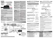
Moun t th e rec e i v e r an d
receiver antenna away from
the MC-9200H/A, motor cord,
power cord, drive battery and
other parts through which a large
If t h e r ece iver is err one ous ly
operated by noise, control will be
lost and is extremely dangerous.
I n s e r t t h e c o n n e c t i o n
If a connector works loose due to
vibration, control will be lost and is
M o u n t t h e M C - 9 2 0 0 H / A
where it will not be exposed
to oil, grease, and water.
the fuselage where there is
an ample flow of cooling air.
Do not wrap the MC-9200H/A
Such wrapping will cause a loss
of cooling effect and the specified
performances will not be obtained.
Install the motor securely.
Also clamp all the cables.
Do no t d is as se mble the
ESC. Do not open the case
Opening the case will damage
the interior. In addition, repair will
A w i t h i n t h e o p e r a t i n g
conditions range given in the
Reverse connection will cause
sparking and immediate destruction
or burning inside the ESC.
bat t e r y, m o t o r, rec e i ver, or
Short circuits will cause sparking
and i mmediate destructi on or
Mount the ESC so that the soldered
part of the cord does not touch
Be careful that no part of
that rotate during operation.
Unexpected rotation may cause
Depending on the receiver, the
motor may rotate the instant the
Do not fly in rainy weather.
If wat er drops e nter th e ESC,
control will be lost due to erroneous
o p e r a t i o n a n d i s e x t r e m e l y
dangero us. I t may also cause
an accident. If the ESC operates
erroneously due to the entry of
water, repair and inspect it.
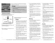
A l w ay s t u r n t h e p o w e r
switches ON and OFF in the
ON: Set the throttle stick to the stop
position and turn on the power
OFF: Set the throttle stick to the
stop position and turn off the power
I f p e r f o r m e d i n r e ve r s e, t h e
propeller may rotate unexpectedly
and is extremely dangerous.
Always remove the battery
I f t h e s w i t c h i s t u r n e d o n
erroneously, the propeller will rotate
unexpectedly or a fire may start.
B e f o r e f l y i n g , c h e c k
operation of the ESC and all
When not set properly and when
a di ff er en t model is selected,
control will be lost and is extremely
Do not touch the motor and
ESC immediately after flight.
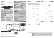
There is no polarity. If the direction of
rotation is opposite, replace any two
Red is positive and black
It is dangerous to make a
Normally, the Receiver power is
supplied from the ESC, and if the
drive battery drops, it becomes an
emergency power supply. Set the
BEC voltage (only the servo works)
slightly higher than this battery
voltage. When the drive battery is
connected, the emergency battery is
Example: 6.6 V LiFe battery
Reverse the throttle channel (CH3) of the Futaba transmitter.
If the temperature becomes high, attach the
attached fan with two screws as shown in the figure.
The attached bifurcated cord is
not normally used. Used when
there is an update of SBM-2.
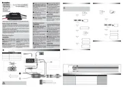
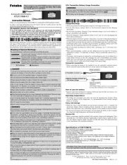
ESC/Transmitter Calibration
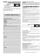
Precautions about Battery F/S
Turn on the transmitter and move the
throttle stick to the high position.
Turn on the transmitter, move the Throttle stick to
the low position, and turn on the throttle cut switch.
If you are in governor mode on a helicopter or use the brakes on an
airplane, set the throttle cut switch on the transmitter. Be sure to connect
the drive battery in the throttle cut state. Release the throttle cut at the
start. After landing, stop the motor with a throttle cut and then remove the
Connect a battery to the ESC, the motor
will sound " ♪ 1-2-3" to indicate the ESC is
Connect a battery to the ESC,
the motor will sound " ♪ 1-2-3"
to indicate the ESC is powered
Turn on throttle cut Throttle Low
5 seconds later, the motor will beep two
short beeps to indicate the maximum
throttle end point is accepted.
The motor will beep "Number" beeps
to indicate the number of Lipo cells
you have plugged in.( ♪ BB indicates
5 cells, B indicates 1 cell)
Long beep sounds to indicate
Move the throttle stick to the bottom position
within 3 seconds after you hear those two beeps,
the minimum throttle position will be accepted
The motor will beep "Number" beeps
to indicate the number of Lipo cells you
have plugged in.( ♪ BB indicates 5 cells, B
The motor will beep a long beep to
indicate the calibration is complete.
Before calibration, set the throttle curve of the transmitter to a straight
line of -100% to 100%, and set all throttle-related mixing to INH. Make
sure that the throttle amount corresponding to the maximum throttle
endpoint and the minimum throttle endpoint of the transmitter is 100%
Perform this calibration when using for the first time or when changing
the set. Let ESC read the operating range of throttle.
The BEC voltage (voltage supplied to the receiver) of this ESC is output
at about 5.0 V for a few seconds at startup, and then the BEC voltage set
by the user is output. Therefore, if the battery fail-safe voltage of the
FASSTest and T-FHSS Air receiver is set to 5.0 V or higher, the Battery F/S
function works even though the battery is sufficient.
* The battery fail-safe voltage of FASST and S-FHSS receivers is fixed at 3.8 V, so
When using with FASSTest or T-FHSS Air, make one of the following set-
1. Reduce the battery fail-safe voltage to 4.8 V or less.
2. Turn off the battery fail-safe setting.
* As a method of monitoring the battery voltage, check the voltage of the receiver
• Power-on Abnormal Voltage Protection
The ESC will measure the input voltage when it’ s connected to a battery or power supply. If the
input voltage is not within the regulated range, it will take the voltage as an abnormal voltage and
then activate the protection, flash Red LED and beep a series of beeps.
The ESC will monitor the motor speed (RPM) during the start-up process. When the speed stops
increasing or the speed increase is not stable, the ESC will take it as a start-up failure. At that time,
if the throttle amount is less than 15%, then the ESC will automatically try to restart up; if it is larger
than 20%, then you need to move the throttle stick back to the bottom position and then restart
up the ESC. (Possible causes of this problem: poor connection/ disconnection between the ESC and
motor wires, propellers are blocked, etc.)
The ESC will gradually reduce the output but won’ t cut it off completely when the ESC temperature
goes above 110° . For ensuring the motor can still get some power and won’ t cause crashes, so
the maximum reduction is about 50% of the full power. The ESC will gradually resume its maximum
power after the temperature lowers down. In addition, the ESC temperature cannot exceed 70°
when it’ s powered on. Otherwise, it cannot be started up but flashes Blue LED and beeps a series of
beeps to indicate the ESC temperature is too high. (Here we are describing the ESC’ s reaction in the
“Soft Cutoff” mode, while if in the “Hard Cutoff” mode; it will immediately cut off the power.)
• Throttle Signal Loss Protection
When the ESC detects loss of signal for over 0.25 second, it will cut off the output immediately to
avoid an even greater loss which may be caused by the continuous high-speed rotation of propeller.
The ESC will resume the corresponding output after normal signals are received.
The ESC will cut off the power/output and automatically restart itself when the load suddenly
increases to a very high value. If the load still remains high or the motor still remains out of sync, then
it will completely cut off the power/output.
• Low-voltage Cutoff Protection
When the operating voltage goes below the preset cutoff voltage, the ESC will gradually reduce the
output but won’ t cut it off completely. For ensuring the motor can still get sufficient power to land
the aircraft safely, so the maximum reduction is about 50% of the full power. You need to change
another fully charged battery to resume the operation when the low-voltage cutoff protection is
• Over-current Protection
During use, the ESC will cut off the output immediately if the current exceeds the regulated value
and then resume it quickly; the ESC will cut off the output completely and won’ t resume it if the
regulated value is exceeded again.
Brushless Electronic Speed