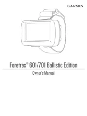
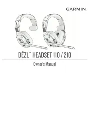
Garmin EchoMAP CHIRP 42 Manual

Garmin Ikke kategoriseret EchoMAP CHIRP 42

Læs gratis den danske manual til Garmin EchoMAP CHIRP 42 (12 sider) i kategorien Ikke kategoriseret. Denne vejledning er vurderet som hjælpsom af 44 personer og har en gennemsnitlig bedømmelse på 5.0 stjerner ud af 22.5 anmeldelser. Har du et spørgsmål om Garmin EchoMAP CHIRP 42, eller vil du spørge andre brugere om produktet?

Side 1/12
echoMAP CHIRP
40/50 Series
Installation Instructions
Important Safety Information
WARNING
See the guide in the Important Safety and Product Information
product box for product warnings and other important
information.
When connecting the power cable, do not remove the in-line
fuse holder. To prevent the possibility of injury or product
damage caused by fire or overheating, the appropriate fuse
must be in place as indicated in the product specifications. In
addition, connecting the power cable without the appropriate
fuse in place voids the product warranty.
CAUTION
Always wear safety goggles, ear protection, and a dust mask
when drilling, cutting, or sanding.
NOTICE
When drilling or cutting, always check what is on the opposite
side of the surface.
To obtain the best performance and to avoid damage to your
boat, install the device according to these instructions.
Read all installation instructions before proceeding with the
installation. If you experience difficulty during the installation,
contact Garmin® Product Support.
Registering Your Device
Help us better support you by completing our online registration
today.
Go to .http://my.garmin.com
Keep the original sales receipt, or a photocopy, in a safe
place.
Contacting Garmin Product Support
Go to for in-country support www.garmin.com/support
information.
In the USA, call 913-397-8200 or 1-800-800-1020.
In the UK, call 0808 238 0000.
In Europe, call +44 (0) 870 850 1241.
Tools Needed
Drill and drill bits
#2 Phillips screwdriver
Marine sealant
3/8 in. wrench or socket
Masking tape
Hardware for the swivel mount (not included)
Self-tapping, pan-head wood screws or pan-head bolts,
either size #8 or a diameter of 5/32 in. (4 mm)
Appropriate washers and nuts (if selecting bolts)
Appropriate drill bit for drilling the pilot hole
Software Update
You may need to update the device software when you install
the device or add an accessory to the device.
Loading the New Software on a Memory Card
You must copy the software update to a memory card using a
computer that is running Windows® software.
NOTE: You can contact Garmin customer support to order a
preloaded software update card if you do not have a computer
with Windows software.
1Insert a memory card into the card slot on the computer.
2Go to .http://www.garmin.com/support/software/marine.html
3Select next to the software bundle that Download
corresponds with your chartplotter.
NOTE: The software download includes updates for all
devices connected to the chartplotter. Select the correct
bundle that corresponds to the chartplotter to be updated.
You can select See All Devices in this Bundle to confirm the
devices included in your download.
4Read and agree to the terms.
5Select .Download
6If necessary, select .Run
7If necessary, select the drive associated with the memory
card, and select > .Next Finish
8Extract the files to the memory card.
NOTE: The software update can take several minutes to load
onto the memory card.
Updating the Device Software
Before you can update the software, you must obtain a
software-update memory card or load the latest software onto a
memory card.
1Turn on the chartplotter.
2After the home screen appears, insert the memory card into
the card slot.
NOTE: In order for the software update instructions to
appear, the device must be fully booted before the card is
inserted.
3Follow the on-screen instructions.
4Wait several minutes while the software update process
completes.
5When prompted, leave the memory card in place and restart
the chartplotter manually.
6Remove the memory card.
NOTE: If the memory card is removed before the device
restarts fully, the software update is not complete.
Mounting Considerations
The device can be mounted using the included bracket, or it can
be mounted flush with the dashboard using a flush-mount kit
(may be sold separately).
Before permanently installing any part of your device, you
should plan the installation by determining the location of the
various components.
The mounting location must provide a clear view of the
screen and access to the keys on the device.
The mounting location must be sturdy enough to support the
device and the mount.
March 2016 Printed in Taiwan 190-01951-02_0B
The cables must be long enough to connect the components
to each other and to power.
The cables can be routed under the bail mount or behind the
device.
To avoid interference with a magnetic compass, the device
should not be installed closer to a compass than the
compass-safe distance value listed in the product
specifications.
Flush Mounting the Device
Before you can flush mount the device, you may need to
purchase a flush-mount kit. The flush-mount kit is not included
with all models.
NOTICE
Be careful when cutting the hole to flush mount the device.
There is only a small amount of clearance between the case and
the mounting holes, and cutting the hole too large could
compromise the stability of the device after it is mounted.
Using a metal pry tool such as a screwdriver can damage the
trim caps and the device. Use a plastic pry tool when possible.
You can mount the device in your dashboard using the flush-
mount template and appropriate hardware.
1Trim the template and make sure it fits in the location where
you want to mount the device.
2Secure the template to the mounting location.
3Using a 9.5 mm (3/8 in.) drill bit, drill one or more of the holes
inside the corners of the solid line on the template to prepare
the mounting surface for cutting.
4Using a jigsaw or rotary cutting tool, cut the mounting surface
along the inside of the solid line indicated on the template.
5Place the device into the cutout to test the fit.
6If necessary, use a file and sandpaper to refine the size of
the hole.
7If your device has trim caps, use a pry tool, such as a flat
piece of plastic or a screwdriver, to carefully pry up the
corners of the trim caps À, slide the pry tool to the center Á,
and remove the trim caps.
8Ensure the mounting holes on the device line up with the pilot
holes on the template.
9If the mounting holes on the device do not line up with the
pilot holes on the template, mark the new pilot-hole locations
on your template.
10 Using a 3.2 mm (1/8 in.) drill bit, drill the pilot holes.
11 Remove the template from the mounting surface.
12 Place the device in the cradle.
13 If you will not have access to the back of the device after you
mount it, connect all necessary cables to the cradle before
placing it into the cutout (Connecting the Cables to the
Cradle, page 3).
NOTE: You must firmly press the connectors through the
appropriate holes in the cradle. If the cables are not pressed
far enough into the cradle, the device appears to lose power
or stop working.
14If necessary, cover unused connectors with weather caps to
prevent corrosion of the metal contacts.
15Install the rubber gasket pieces on the back of the cradle.
The pieces of the rubber gasket have adhesive on the back.
Make sure you remove the protective liner before installing
them on the device.
16Place the device and cradle into the cutout.
17Secure the device to the mounting surface using the included
screws.
18Install the trim caps by snapping them in place around the
edges of the device.
Installing the Swivel Base
Preparing to Run Cables under the Mounting Surface
NOTICE
Use pan-head screws or bolts when securing the swivel-mount
base. Screws or bolts with countersunk heads damage the
base.
Before you can prepare the swivel-mount base, you must
choose the location to install the mount and decide whether to
attach the mount using screws or bolts.
1Remove the 10 mm M6x1 Phillips screw À and separate the
swivel mount Á from the base Â.
2Orient the swivel base so the pass-through holes à face the
desired direction.
3Using the swivel base as a template, mark the pilot hole
locations Ä.
4Mark the cable routing hole Å.
2


Produkt Specifikationer

Mærke: Garmin
Kategori: Ikke kategoriseret
Model: EchoMAP CHIRP 42

Har du brug for hjælp?

Hvis du har brug for hjælp til Garmin EchoMAP CHIRP 42 stil et spørgsmål nedenfor, og andre brugere vil svare dig


Ikke kategoriseret Garmin Manualer

Ikke kategoriseret Manualer

Nyeste Ikke kategoriseret Manualer