Gigabyte R282-Z97 Manual
Læs gratis den danske manual til Gigabyte R282-Z97 (152 sider) i kategorien Server. Denne vejledning er vurderet som hjælpsom af 16 personer og har en gennemsnitlig bedømmelse på 4.6 stjerner ud af 8.5 anmeldelser.
Har du et spørgsmål om Gigabyte R282-Z97, eller vil du spørge andre brugere om produktet?

Produkt Specifikationer
| Mærke: | Gigabyte |
| Kategori: | Server |
| Model: | R282-Z97 |
Har du brug for hjælp?
Hvis du har brug for hjælp til Gigabyte R282-Z97 stil et spørgsmål nedenfor, og andre brugere vil svare dig
Server Gigabyte Manualer


Server Manualer
- Netgear
- Eaton
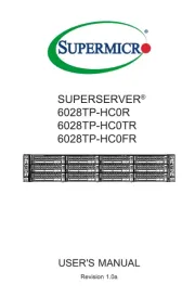
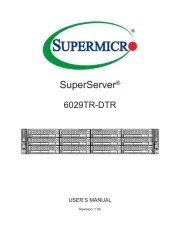
- Supermicro
- Geovision
- Lantronix
- Smart-AVI
- Sitecom
- Silverstone
- Luxman
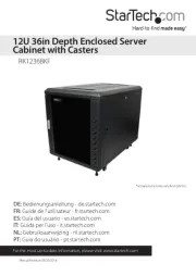
- StarTech.com
- Dell
- Atlona
- In Win
- Lenovo
- Ibm
Nyeste Server Manualer