Gira 0394 Manual


Læs gratis den danske manual til Gira 0394 (5 sider) i kategorien Termostat. Denne vejledning er vurderet som hjælpsom af 27 personer og har en gennemsnitlig bedømmelse på 4.4 stjerner ud af 14 anmeldelser. Har du et spørgsmål om Gira 0394, eller vil du spørge andre brugere om produktet?

Side 1/5
GIRA
Info
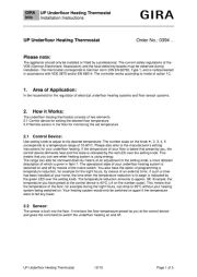
UP Underoor Heating Thermostat
Installation Instructions
UP Underfloor Heating Thermostat Order No.: 0394 ..
Please note:
The appliance should only be installed or fitted by a professional. The current safety regulations of the
VDE (German Electricians Association) and the local electricity boards must be observed during
installation. The thermostat corresponds to German norm DIN EN 60730, Type 1, and is radioscreened
in accordance with VDE 0875 and/or EN 66014. The controller works according to mode of action 1C.
1. Area of Application:
In the household for the regulation of electrical underfloor heating systems and floor sensor systems.
2. How it Works:
The underfloor heating thermostat consists of two elements:
2.1 Control device for setting the desired floor temperature.
2.2 Remote sensor in the floor for monitoring the set temperature.
2.1 Control Device:
Use setting knob to adjust to the desired temperature. The number scale on the knob , 2, 3, 4, 5
corresponds to a temperature range of 10 50°C. Please also refer to the manufacturers setting -
instructions for your underfloor heating. If the temperature of your floor is below that preset by you, the
control device demands heat and this state is indicated by the red LED over the setting knob. This
means that you can see when heating system is using energy.
The range can also be narrowed down by means of an adjustment to the setting knob, a more detailed
description of which is given in Item 7. The operational state of your underfloor heating system is
switched on and off by means of the mains switch. You also have the option of programming a
temperature reduction, for example for the night hours, by means of an external timer. If such a timer
has been installed at your home, the time when the temperature reduction is to begin is indicated by
the green LED over the setting knob. The temperature reduction amounts to approx. 5K. Example: the
temperature you have preset at the control device is 40°C (=4 on the number scale). This means that
the temperature of the floor, for example during the night hours, can drop to 35°C without your heating
system being switched on. Your heating system would only be switched on again if the temperature
were to fall any lower.
2.2 Sensor:
The sensor is built into the floor. It monitors the floor temperature preset by you at the control device
and gives the command to switch the underfloor heating on and off.
UP Underfloor Heating Thermostat 12/13 Page of 1 5
GIRA
Info
UP Underoor Heating Thermostat
Installation Instructions
3. Installation
3.1 Control Device: on a commercially available concealed socket, Ø 55.
Caution! The device should always be installed with its retaining ring on top of the wallpaper.
a) Remove housing cover. Pull off setting knob. Loosen lid screw. Remove lid.
b) Electrical supply: in accordance with circuit diagram; solid conductor section 1 to 2,5 m. No -
earth lead required. Earth lead terminals is only used for looping through.
When mounted properly, the requirements of protection class II are fulfilled.
c) - Fit the thermostat on to the socket using a thread moulding Flush mounted socket screw.
d) Put on housing lid. To do this, the lid must slot into the top left of the housing base.
e) Continue as under a) but in the opposite direction.
3.2 Sensor:
The sensor must fulfil the requirements of protection class II and absolutely must be laid in a protective
tube, together with sensor cable H03VV. In this way, the sensor is protected from damp and can easily
be replaced in the event of repair.
4. Instructions for the Fitter
- -The I O switch on the control device is a single pole switch disconnecting the device from the
mains and interrupting the electric circuit to the heating resistor in the floor.
For work on the load circuit, the power supply must at all times be disconnected. e.g. the fuse
removed.
-The relay contact is closed when the sensor is disconnected, when the sensor is short circuit, the
relay contact is open.
Caution!
In the event of a fault, electric potential may be present at the sensor.
5. Specifications
5.1 Control Device:
Order reference 0394 ..
Operating voltage AC 230 V 50 Hz
Permissible variation AC 195...253 V 50 Hz
Temperature range (number scale) , 4, 5 (= 10...50° C) , 2, 3
Switching current at AC 250 V 10 (4) A cos ϕ= 1
Breaking capacity 2,3 kW
Rated surge voltage 4,000 V
Switch Mains, "On/Off"
Red LED indicator Control device demands heat (heating operation)
Green LED indicator Temperature reduction "O N"
Contact (relay) 1 make contact (for heating) (not floating)
Temperature reduction (TA) approx. 5 K
Switching temperature difference approx. 1 K
Protective system conformity with EN 60529 housing in IP 20
Operating temperature T 40
Storage temperature 5 T 70 -2
UP Underfloor Heating Thermostat 12/13 Page of 2 5


Produkt Specifikationer

Mærke: Gira
Kategori: Termostat
Model: 0394

Har du brug for hjælp?

Hvis du har brug for hjælp til Gira 0394 stil et spørgsmål nedenfor, og andre brugere vil svare dig


Termostat Gira Manualer

Gira

Gira 039601 Manual

22 Juli 2025
Gira

Gira 039227 Manual

22 Juli 2025
Gira

Gira 237003 Manual

21 September 2024
Gira

Gira 0393 Manual

19 September 2024
Gira

Gira 0396 Manual

18 September 2024
Gira

Gira 0394 Manual

26 August 2024
Gira

Gira 0392 Manual

5 August 2024
Gira

Gira 0390 Manual

4 August 2024
Gira

Gira 039703 Manual

3 August 2024
Gira

Gira 0391 Manual

2 August 2024

Termostat Manualer

Nyeste Termostat Manualer