2.2 Use for other than intended pur-
2.3 Liability and guarantee
3.3 Symbols on the instrument or in
the operating instructions
4.1 Auto power on / switching on
5.3 Single-pole phase test
10. Contact, support and service
Read and follow these instructions carefully and com-
pletely in order to ensure safe and proper use.
The instructions must be made available to all persons
Keep for future reference.
The testers have been constructed and tested in
accordance with the safety regulations for voltage
testers and have left the factory in a safe and perfect
Depending on the internal impedance of the volt-
age tester, there will be a different indications of the
presence or absence of operating voltage in case of
The device may onlybeused by qualiedelectri-
ciansinthecommercialeld.
A voltage tester of relatively low internal impedance,
comparedtothereferencevalueof100kΩ,willnot
indicate all interference voltages having an original
voltage value above the ELV level. When in contact
with the parts to be tested, the voltage tester may
discharge the interference voltage to a level below
the ELV temporarily, but it will be back to the original
value when the voltage tester is removed.
When the indication “voltage present” does not ap-
pear, it is highly recommended installing earthing
A voltage tester of relatively high internal imped-
ance,comparedto thereferencevalueof100kΩ,
will not clearly indicate the absence of operating
voltage if interference voltage is present.
When the indication “voltage present” appears on an
installation part that is expected to be disconnected,
itishighly recommendedto conrmthrough other
means (e. g. use of an adequate voltage tester,
visual check of the disconnecting point of the elec-
tric circuit, etc.) that there is no operating voltage on
theparttobetestedandtoconrmthatthevoltage
indicated by the voltage detector is an interference
A voltage tester declaring two values of internal im-
pedance has passed a performance test of manag-
ing interference voltages and is (within its technical
limits) able to distinguish operating voltage from
interference voltage and can directly or indirectly
indicate which type of voltage is present.
Danger of electric shock and other dangers
To avoid an electric shock, observe the precautions
when working with voltages exceeding 120 V (60 V)
DC or 50 V (25 V) eff AC. In accordance with DIN
VDE these values represent the threshold contact
voltages (values in brackets refer to limited ranges,
e. g. in agricultural areas).
The tester must not be used with the battery com-
Before each test, ensure that the test lead and de-
vice are in perfect working order. Check for broken
cables, leaking batteries etc.
Hold the tester and accessories by the designated
grip areas only, the display elements must not be
covered. Never touch the test probes.
The tester may be used only within the specied
measurement ranges and in low-voltage installa-
The tester may be used only in the measuring cate-
gory it has been designed for.
Before and after use, always check that the tester
is in perfect working order (e. g. on a known voltage
The tester must no longer be used if one or more
functions fail or if does not appear to work.
The tester must not be used in rain or precipitation.
A correct display is guaranteed only within a temper-
ature range of –15° C to +55° C and a relative air
If the safety of the user cannot be guar-
anteed, the tester must be switched
off and secured against unintentional use.
Safety is no longer guaranteed in the following cases:
– if the tester can no longer perform the
−ifthetesterwasstoredfortoolonginunfavorable
The tester complies with all EMC regulations.
Nevertheless, in rare cases it may disturb electric
deviceswithitselectricaleldorthetestermaybe
disturbed by electrical devices. .
Never use the tester in explosive environments.
Tester must be operated by trained users only.
Operational safety is no longer guaranteed if the
testerismodiedoraltered.
The tester may be opened by an authorized service
The current test may only be performed on double
Please read this important information!
2.1 Intended use / Use for intended purpose
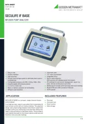
The METRALINE VC SENSE is an universal applicable
testerforvoltage,current,continuityandrotaryeldtest-
ing, and for various additional tests. The tester is con-
structed according to the latest safety regulations and
guarantees safe and reliable working.
Safety of the user, as well as that of the instrument, is only
assured when it’s used for its intended purpose.
2.2 Use for other than intended purpose
Using the instrument for any purposes other than those
described in these instrument operating instructions is
contrary to use for intended purpose. Use for purposes
other than those intended may result in unforeseeable
2.3 Liability and guarantee
The warranty provided by Gossen Metrawatt GmbH, and
its liability, are governed by the applicable contractual
and mandatory statutory provisions.
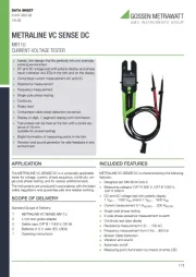
1 METRALINE VC SENSE (M611L)
2 protective caps CAT III / 1000 V, GS 38
2 batteries (1.5 V, AAA, IEC LR03)
1 operating instructions (this document)
Please check the scope of delivery for completeness
1. Opening for current measurement
2. Marking for middle position of measured cable
3. Cable break detection sensor area
5. Test leads (clipped onto back side)
7. On/off and function button
8. Torchlight and function button
10. Test lead positions to ensure a 19 mm distance be-
tween the test tips for socket testing
2. Polarity indication (120 V LEDs)
3. ELV / LED for single-pole phase test
2. AC/ DC and polarity symbols
3. Function symbols (from left to right, upper row:
voltage test, current test, test of voltages < 10 V, re-
sistance test; lower row: diode test, frequency test,
4. Low battery indication
5. 4-digit 7-segment display
3.3 Symbols on the instrument or in the
Warning of a potential danger. Read and follow the
Note! Please use utmost attention.
Caution! Dangerous voltage. Danger of electrical
Continuous double or reinforced insulation category
II IEC 536 / DIN EN 61140.
Suitable for working under live voltage.
Conformity symbol, the instrument complies with
the valid EU directives. It complies with the EMC
Directive (2014/30/EU), DIN EN IEC 61326-1,
the Low Voltage Directive (2014/35/EU), and
DINEN61243-3.You cannd theCE declaration
The instrument may not be disposed of with house-
hold trash. You are required to comply with all appli-
cable local regulations. Further information regard-
ing disposal can be found on our website.
METRALINE VC SENSE is characterized by the follow-
●DesignedtomeetDINEN61243-3
●MeasurementcategoryCATIV/600V
●MeasurementcategoryCATIII/1000V
●ACandDCvoltagetestupto1000V
●Currenttestupto200A
●Single-polephasetest
●Two-polephaserotationdeterminationagainstearth
●IP64protection(DINEN60529)
LED nominal voltage 120 V / 230 V / 400 V / 690 V / 1000 V
LED tolerances DIN EN 61243-3
ELV indication LED > 50 V
Response time <1 s at 100 % of each nominal value
±3 % ±1.5 V (1 V … 29.9 V)
±3 % ±3 dgt (30 V … 1500 V)
Frequency range 45 HZ … 65 Hz
Measuring operation 30 s ON, 240 s OFF
170 V … 1000 V phase-to-phase, AC
Continuity test 0kΩ…500kΩ+50%
accuracy: ±5 % ±10 dgt at 25° C;
resolution:1Ω(1Ω…2000Ω)
1 Hz … 800 Hz ±5 % ±5 dgt;
Battery 3 V (2 × IEC LR03, 1.5 V)
Humidity max. 85 % relative humidity
Overvoltage CAT IV / 600 V, CAT III / 1000 V
Standards applied DIN EN 61243-3
• The tester switches on when it detects continuity , or
an AC or DC voltage of above approx. 6 V, or a live
• The tester can be switched on with a button.
• The tester automatically powers off after approx.10 sec
of no signal at the test tips.
• The torch light automatically switches off after approx.
• Connect both test tips to the object under test. The test
probes can by held by hand or clipped to the tester. If
they are clipped onto the tester, they have a distance of
19 mm to contact sockets one-handed.
• The voltage is indicated by LEDs and on the LCD.
• The buzzer and vibration turn on if the voltage is higher
• The voltage polarity is indicated on the LCD as follows:
-DC: – symbol and DC symbol are on
• The polarity is indicated with the LEDs (above 120 V):
AC: + and – 120 V LEDs are on
When the L2 probe is the positive (negative) po-
tential, the polarity indication LED indicates “+DC”
During the voltage test, the L or R LED may light up.
In case of empty batteries, only the ELV LED lights
Low voltage mode – 1 V … 1000 V
• Press On/Off/Function button repeatedly until the LCD
• In this mode AC and DC voltage beginning at 1 V
• Connect both probes to the object under test.
• All indications are described in 5.1.
Continuity mode is disabled in low voltage mode.
• Press On/Off/Function button repeatedly until the LCD
• In current test mode, currents between 0.1 A … 200 A
• The cable needs to be positioned in the center of the
opening at the height of the markings left and right.
• Only double insulated cables may be measured.
• Store the test probes safely to avoid any unintended
• If a voltage of approx. 6 V is detected between the test
tips, the tester switches to voltage measurement.
5.3 Single-pole phase test
The current test accuracy depends on the cable
positionintheopeningandonpossiblestrayelds
around the tester. Best results are achieved if the
middle point of the measured cable is aligned with
the markings on the fork.
Proper functioning cannot be guaranteed if the
grounding conditions aren’t good.
The single-pole phase test must not be used to test
systems or system components for the absence of
•Holdthetesterrmlyinyourhand.ConnecttheL2test
tip to the object under test. The live circuit LED lights
probes and the buzzer sounds when a voltage of ap-
or more exists in the object under test.
• The phase rotation tests only gives reliable results for
grounded three-phase systems.
•Holdthetesterrmlyinyourhandandconnectbothtest
probes to the object under test.
• The phase-to-phase voltage is indicated by the voltage
•TheRLEDlightsupforrightrotaryeld.
•TheLLEDlightsupforleftrotaryeld.
• Measurement principle: The instrument detects the
phase rising order to earth.
Proper functioning cannot be guaranteed if the
grounding conditions aren’t good.
Make sure the object under test isn’t live (test for the
• Use a two-pole voltage test to ensure that the test ob-
• Connect both test probes to the object under test. The
continuity LED lights up and the buzzer sounds if the
resistanceisbelow500kΩ.
• The continuity test is performed in all operating modes
except low voltage mode and resistance testing.
• If a voltage of approx. 6 V is detected between the test
tips, the tester switches to voltage measurement.
• If a lower threshold for continuity is preferred, low
continuity mode can be selected.
• Press the On/Off/Function button repeatedly until the
LRx symbol is shown on LCD.
• Connect both test probes to the object under test. The
continuity LED lights up and the buzzer sounds if the
resistanceisbelow20kΩ.
Make sure the object under test isn’t live (test for the
• Switch into diode testing mode by pressing the On/Off-/
Function button repeatedly until symbol is shown
• Connect the test probes to the diode under test.
The continuity LED lights up and the buzzer
sounds when L1 is connected to the anode and
Continuity indication will be off if L1 tip is connect-
ed on Cathode of diode and L2 tip on Anode.
If a voltage of approx. 6 V is detected between the
test tips, the tester switches to voltage measure-
Make sure the object under test isn’t live (test for the
• Press the On/Off/Function button repeatedly until the
kΩsymbolisshownontheLCD.
• Connect the test probes to the object under test. Meas-
uredresistance ofup to100 kΩis beshown onthe
•For resistance ~20 Ω the buzzer sounds to indicate
If a voltage of approx. 15 V is detected between the test
tips, the tester switches to voltage measurement.
• Press the On/Off/Function button repeatedly until the
Hz symbol is shown on the LCD.
• Connect the test probes to the object under test. For
AC voltage, frequencies 1 Hz … 800 Hz are be shown
• Frequency measurement is possible for voltages > 10 V
The voltage is indicated if > 120 V. The ELV diode
will indicate voltages > 50 V
• Press the Torchlight/Function button to turn on the
light. The LED will light up for approx. 30 s.
• Press the button to turn it off sooner.
• All LEDs, LCD segments, the vibration, the torch light,
and the buzzer are turned on for 1 s after battery re-
• In addition, a self test can be performed:
Shorten the probe tips while turning the tester
OFF. Let if remain off for 30 seconds before turn-
ing it on again by shorting the probe tips again.
If the HOLD function is activated, only the last saved
measured value is displayed on the LCD. The LCD
will no longer be updated, even if the applied voltage
changes. The LED display always shows the current
voltage (> 120 V). The ELV diode indicates danger-
• By pressing the Torchlight/Function button long (2
seconds), the HOLD function activates and freezes the
display value. A short buzz will indicate that the function
hasbeenactivated.BybrieypressingtheTorchlight/
Function button, the frozen display is released. When
the HOLD function is active, the symbol is
• The backlight is turned on when torch light is turned on.
The tester must not be used with the battery com-
partment open. The batteries must be replaced, if
the continuity test LED does not light up when the
test tips are shortened. Also, the low battery symbol
Follow the procedure below to replace the batteries
with new ones (type AAA, IEC LR03, 1.5 V).
1. Unscrew the battery compartment.
2. Remove the batteries and insert new batteries. Pay
attention to the polarity indication of the battery com-
3. Insert the battery compartment lid and tighten the
Conrm that the battery compartment is properly
locked prior to conducting tests.
Damage to the product and measuring error due to
environmentalinuences.Storetheinstrumentina
protected location and only within the limits of per-
missible ambient conditions.
Damage to the product and measuring error. Trans-
port the instrument only within the limits of permis-
sible ambient conditions (temperature, humidity,
etc.). Only transport the instrument with sufcient
Remove batteries when the instrument will not be in
use for a longer period in order to prevent possible
hazard or damage due to potentially leaking batteries.
If the instrument is dirty after daily usage, it is advised
to clean it by using a moist cloth and a mild household
Danger of death due to electrical shock
Prior to cleaning, ensure that instrument is switched
off and disconnected from the external voltage sup-
ply and any other instruments (such as DUTs, con-
Never use acid detergents or dissolvent for clean-
If your instrument requires repair, please contact our ser-
Loss of warranty and guarantee claims
Unauthorizedmodicationoftheinstrumentispro-
hibited. This also includes opening the instrument.
If it can be ascertained that the tester has been
opened by unauthorized personnel, no guarantee
claims can be honored by the manufacturer with
regard to personal safety, measuring accuracy,
compliance with applicable safety measures or any
The device may only be repaired or opened by author-
ized,qualiedpersonnelwhoarefamiliarwiththeasso-
ciated dangers. Original replacement parts may only be
installedbyauthorized,qualiedpersonnel.
10. Contact, support and service
Gossen Metrawatt GmbH can be reached directly and
simply – we have a single number for everything! Wheth-
er you require support or training, or have an individu-
al inquiry, we can answer all of your questions here:
Monday to Thursday: 8 a.m. to 4 p.m.
Or contact us by e-mail at: info@gossenmetrawatt.com
Do you prefer support by e-mail?
Measuring and Test Technology:
support@gossenmetrawatt.com
Industrial Measuring Technology:
support.industrie@gossenmetrawatt.com
Please contact GMC-I Service GmbH for repairs, re-
placement parts and calibration1:
Beuthener Str. 41, 90471 Nürnberg, Germany
service@gossenmetrawatt.com
https://www.gmci-service.com/en/
1 DAkkS calibration laboratory per DIN EN ISO/IEC 17025
accredited by the Deutsche Akkreditierungsstelle GmbH
under reference number D-K-15080-01-01.
Prepared in Germany • Subject to change, errors excepted •
A pdf version is available on the Internet
All trademarks, registered trademarks, logos, product names,
and company names are the property of their respective ow-