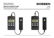
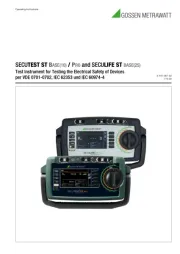
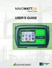
2 | 168 PROFITEST PRIME / PROFITEST PRIME AC
TABLE OF CONTENTS
1 Safety Instructions.............................................................. 6
2 Applications ........................................................................ 8
2.1 Intended Use / Use for Intended Purpose .......... 8
2.2 Use for Other than Intended Purpose................. 8
2.3 Liability and Guarantee....................................... 8
3 Documentation.................................................................... 9
3.1 Information Concerning these Instructions.......... 9
3.2 Scope of Validity ................................................ 9
3.3 Identification of Warnings ................................... 9
3.4 Symbols in the Documentation .......................... 9
3.5 Definition of Terms ........................................... 10
3.6 List of Abbreviations and their Meanings in the
Same Order as the Rotary Switch Positions ..... 10
4 Getting Started.................................................................. 11
5 The Instrument.................................................................. 12
5.1 Scope of Delivery ............................................. 12
5.2 Optional Accessories ....................................... 12
5.3 Included Features ............................................ 13
5.4 Scope of Functions Depending on Type of
Power Supply .................................................. 14
5.5 Instrument Overview ........................................ 15
5.5.1 Connection, Control and Display Panel,
PROFITEST PRIME................................... 15
5.5.2 Connection, Control and Display Panel,
PROFITEST PRIME AC ............................. 16
5.5.3 Control and Display Panel ......................... 17
5.5.4 Signaling via LEDs .................................... 19
5.5.5 Indications at the Display .......................... 21
5.5.6 Overview of Device Settings and
Measuring Functions................................. 25
5.5.7 Probe Functionality ................................... 26
5.5.8 Symbols on the Instrument and the
Included Accessories................................ 27
5.6 Relevant Standards.......................................... 28
5.7 Technical Data ................................................. 29
5.8 Characteristic Values........................................ 31
5.8 U...................................................................... 31
5.8 Rlo 0.2 A.......................................................... 31
5.8 RLO 25 A......................................................... 31
5.8 RISO ............................................................... 32
5.8 Rins ................................................................ 32
5.8 RCD IF ............................................................ 33
5.8 RCD I
Δ
N .......................................................... 34
5.8 RCD IF + IΔ
N.................................................................35
5.8 ZLOOP AC/DC ............................................... 36
5.8 ZLOOP DC+ ................................................... 37
5.8 Zloop Z+Rlo .................................................... 37
5.8 ZLOOP *.......................................................... 37
5.8 Ures ................................................................ 38
5.8 IMD ................................................................. 38
5.8 RCM................................................................ 39
5.8 IL 1.................................................................. 39
5.8 ≤1V
1) ........................................................................... 40
5.8 T % r.h. ........................................................... 40
5.8 EXTRA
Δ
U ........................................................ 40
6 Initial Startup (supply voltage) ..........................................44
6.1 General Information ......................................... 44
6.2 Using the Measuring/Test Instrument with Mains
Power (auxiliary power) .................................... 44
6.3 Using the Measuring/Test Instrument in Battery
Mode............................................................... 44
6.4 Standby function ............................................. 45
7 Connecting Probes and Other Accessories .......................46
7.1 General............................................................ 46
7.2 Probes and Probe Attachments....................... 46
7.2.1 Standard Measuring Probes
(included in scope of delivery)................... 46
7.2.2 Measuring Probes with Longer Connector
Cables (optional accessory)...................... 46
7.2.3 Intelligent Measuring Probe I-SK4-PROFI-
TEST-PRIME (Z506T) or
ISK-12-PROFITEST-PRIME (Z506U)
(optional accessory).................................. 46
7.2.4 Probe Attachments (optional accessories) 46
7.3 Current Clamp Sensors (optional accessories). 47
7.4 Adapters (optional accessories) ....................... 47
7.5 Sensors ........................................................... 47
7.6 High-Voltage Accessories for the PROFITEST
PRIME AC ....................................................... 47
7.7 Barcode Reader / Scanner .............................. 47
7.8 Bluetooth® Keyboard...................................... 47
8 Test Instrument Settings – Setup......................................49
9 Internal Database ..............................................................54
9.1 Creating Distributor Structures, General........... 54
9.2 Creating a Distributor Structure at the Measuring/
Test Instrument ............................................... 54
9.2.1 Overview of the Meanings of Icons used to
Create Structures ..................................... 54
9.2.2 Creating a Structure (based on the example
of an electric circuit).................................. 56
9.3 Searching for Structure Elements .................... 57
10 General Notes Concerning Measurements........................58
10.1 Help Function .................................................. 58
10.2 Automatic Settings, Monitoring and Shutdown 58