Gossen Metrawatt PROFITEST PV Manual
Gossen Metrawatt
Måleudstyr
PROFITEST PV
Læs gratis den danske manual til Gossen Metrawatt PROFITEST PV (36 sider) i kategorien Måleudstyr. Denne vejledning er vurderet som hjælpsom af 25 personer og har en gennemsnitlig bedømmelse på 5.0 stjerner ud af 13 anmeldelser. Har du et spørgsmål om Gossen Metrawatt PROFITEST PV, eller vil du spørge andre brugere om produktet?
Side 1/36

Operating Instructions
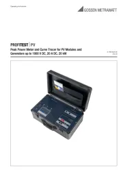
PROFITESTPV
Peak Power Meter and Curve Tracer for PV Modules and
Generators up to 1000 V DC, 20 A DC, 20 kW 3-349-633-03
3/3.16

2 GMC-I Messtechnik GmbH
Contents Page Contents Page
1 License Agreement .......................................................... 3
2 Introduction ...................................................................... 4
3 Use for Intended Purpose ................................................. 4
4 Safety Precautions ........................................................... 4
4.1 Safety Features and Precautions .....................................................4
5 Warnings .......................................................................... 5
6 Operating the PROFITEST PV ............................................ 6
6.1 Controls and Connectors ................................................................6
6.2 General Notes ...............................................................................6
6.3 Connecting Peripheral Devices .......................................................6
6.4 Power Supply ................................................................................7
6.5 Connection to a PC ........................................................................7
6.6 Connecting the Solar Generator ......................................................7
6.7 Measured Value Transducers for Temperature and
Irradiation ......................................................................................7
6.8 Switching the Instrument On ..........................................................8
6.9 Buttons .........................................................................................8
6.10 Measurement ................................................................................9
6.10.1 Entering Module, Customer and System Data ..................................9
6.10.2 Start Measurement ........................................................................9
6.10.3 Archive .........................................................................................9
6.10.4 Transfer ......................................................................................10
6.10.5 Results .......................................................................................10
6.11 Messages ...................................................................................10
7 1000 V / 32 A Load Disconnector ................................... 11
8 Influences on Measuring Accuracy ................................ 11
9 Installing PV Analyzer Transfer Software ....................... 12
10 Installing the USB Device Driver (CDM) .......................... 13
10.1 Installation via “Found New Hardware” ..........................................13
10.2 Uninstalling the CDM Driver ..........................................................14
11 Using PV Analyzer Transfer Software ............................ 15
11.1 The File Menu .............................................................................15
11.1.1 Open ..........................................................................................15
11.1.2 Save as ... ...................................................................................15
11.1.3 Browse .......................................................................................15
11.1.4 Export .........................................................................................16
11.1.5 Report .........................................................................................16
11.1.6 Analysis ......................................................................................17
11.1.7 Printer Setup ...............................................................................17
11.1.8 Exit .............................................................................................17
11.2 Edit .............................................................................................17
11.2.1 Cut .............................................................................................17
11.2.2 Copy ...........................................................................................17
11.2.3 Paste ..........................................................................................17
11.3 Extras .........................................................................................17
11.3.1 Start Measurement at the PROFITEST PV
(“Trace Curve” button). ................................................................17
11.3.2 Managing Files at the PROFITEST PV (“Data Transfer” button) ...18
11.3.3 Transfer Date and Time to the PROFITEST PV ..............................18
11.3.4 Continuous Measurement ............................................................18
11.3.5 Editing the PROFITEST PV Sensor Database .................................19
11.3.6
Managing Modules at the PROFITEST PV
(“Module List” button) ........................................................................19
11.3.7
Managing Measuring Tasks at the PROFITEST PV
(“Measuring Tasks” button) ................................................................19
11.3.8 Calculating Internal Series Resistance Rs ......................................19
11.3.9 Customer Database .....................................................................20
11.3.10 Module Database ........................................................................20
11.3.11 Settings ......................................................................................20
11.3.12 Setting Temperature Offset ..........................................................21
11.3.13 Firmware Update .........................................................................21
11.4 Using the Graphic Interface ..........................................................21
11.4.1 Measuring Points On/Off (“Measuring Points” button) ....................21
11.4.2 MPP On/Off (“Show MPP” button) ................................................21
11.4.3 Display Theoretical Curve On/Off ..................................................21
11.4.4 Display Characteristic STC Curve On/Off .......................................21
11.4.5 Power Display On/Off ...................................................................21
11.4.6 Key On/Off (“Key” button) .............................................................22
11.4.7 Stretch On /Off (“Max. Zoom” button) ...........................................22
11.4.8 To Clipboard (“Clipboard” button, main toolbar) .............................22
11.5 Results .......................................................................................22
11.6 Help ...........................................................................................22
11.6.1 Contents .....................................................................................22
11.6.2 Search ........................................................................................22
11.6.3 Using Help ..................................................................................22
11.6.4 Info .............................................................................................22
12 Technical Data ............................................................... 23
12.1 Unit of Measure ...........................................................................23
12.2 Sensor Connection Pin Allocations ................................................23
12.3 Computer Unit .............................................................................23
12.4 Display .......................................................................................23
12.5 Operation ....................................................................................23
12.6 Power Supply ..............................................................................23
12.7 Dimensions .................................................................................23
12.8 Operating Conditions ...................................................................23
12.9 Optionally Available .....................................................................23
13 List of Symbols Used in Formulas .................................. 24
14 Causes of Reduced Output and Yield ............................. 25
15 Characteristic IU Curves: Contexts ................................. 26
16 Sample Characteristic Curves from Actual
Practice (source: PVE) ..................................................... 29
17 Glossary ......................................................................... 30
18 Appendix A ..................................................................... 32
18.1 Charge Level Indicator for Integrated Rechargeable Battery ............32
18.2 Acoustic Signals ..........................................................................32
19 Maintenance and Recalibration ..................................... 33
19.1 Return and Environmentally Sound Disposal ..................................33
19.2 Recalibration ...............................................................................33
19.3 Repair and Replacement Parts Service
Calibration Center and Rental Instrument Service ..........................33
20 Product Support ............................................................. 34

4 GMC-I Messtechnik GmbH
2 Introduction
The PROFITEST PV allows for the measurement of the characteristic IU
curves of photovoltaic modules and strings. Thanks to a new process, the
instruments are capable of calculating peak power, internal series resistance Rs
and shunt resistance Rp on the basis of measured values directly at the PV sys-
tem’s installation site, and displaying them at the color graphic display.
Peak power is power achieved by a module under standard test conditions (STC)
[1]. Until recently, the measurement of peak power was only possible by means
of a complex procedure in specially equipped laboratories. Thanks to a patented
process developed by Professor Dr. Wagner at the university of applied sciences
in Dortmund, Germany, this measurement can now be easily performed with
the PROFITEST PV. Quality control for PV systems is thus quick and eco-
nomical without a long learning curve. In actual practice, this simple yet deci-
sive test assures safety for the customer and for the installer. Beyond this,
acquired characteristic curves make it possible to draw further conclusions
regarding the electrical characteristics of the measured module or string. And
thus the PROFITEST PV is also suitable for use in research and develop-
ment.
The PROFITEST PV is a portable measuring instrument with inte-
grated battery (supply power) in a sturdy housing. The instrument
is equipped with its own miniature industrial PC and a high-con-
trast, color graphic, daylight-compatible LCD, and can thus be
used independent of additional devices. However, a PC can be
connected via a standard USB port if required for data transmis-
sion and further analysis of the measured values.
The PROFITEST PV is operated conveniently via a touch-screen
and a menu. The functions are designated in a self-explanatory
fashion with simple pictograms, and the user is prompted contin-
uously by the software. The leaning curve for becoming familiar
with instrument operation is practically non-existent.
All commercially available irradiation sensors can be connected to
the instrument, which generate a voltage of approximately 0 to
100 mV with linear dependence on irradiation (Phox sensors).
Depending on instrument variant, an additional Pt100 sensor can
also be connected. This makes it possible to measure module
temperature, and is mounted to the back of the module.
Measurement Description
The PROFITEST PV automatically measures the characteristic
current-voltage curve of the generator at a capacitive load, as well
as momentary temperature and irradiation at the point in time of
measurement, and calculates the effective solar cell curve, P
pk,
Rp and Rs, on the basis on the measured values [2][3]. Measure-
ment data are saved to continuously battery-backed memory
after measurement, and can thus be retrieved again later (for
example at the office) [4]. The instrument has enough internal
memory storage capacity for several thousand measurements.
The following values are displayed as results:
Absolute values:
• Peak power PPk
• Internal series resistance R
s
• Parallel internal resistance (shunt resistance) R
p
Instantaneous values:
• Upmax, Ipmax, Pmax,
• Uoc, Isc, FF, Tmod, ETRMS
If desired, the ascertained characteristic IU curve appears directly
at the integrated, high resolution color graphic display.
3 Use for Intended Purpose
The PROFITEST PV peak power meter and characteristic curve
tracer is used exclusively for recording IC curves of individual pho-
tovoltaic modules and strings. Before the device under test is
connected to the measuring instrument, it must be assured that
the DUT cannot, at any time, exceed the measuring instrument’s
maximum permissible current and voltage values.
4 Safety Precautions
Before initial startup of the measuring instrument, read through
the included operating instructions completely in any case,
because it contains important information for the prevention of
damage to the measuring instrument and personal injury! Keep
this manual together with the PROFITEST PV.
Instructions regarding safety are identified with symbols signifying
“Caution!” or “Caution: High-Voltage!,” and must be carefully
adhered to. Damages resulting from non-compliance with these
instruction are excluded from the guarantee. No liability is
assumed for consequential damages.
PV Analysator software necessitates a PC with hard disk and MS
Windows Vista, 7 or 8, as well as a mouse for control purposes.
An available USB port is required in order to connect the
PROFITEST PV to the PC.
Available space on the hard disk required for PV Analysator soft-
ware amounts to roughly 10 MB prior to installation. Make sure
that there is always adequate hard disk memory capacity for sub-
sequent storage of data.
Caution!
!
We would like to draw attention to the fact that, for pur-
poses of data security, it’s very important to create a
backup for program data on separate data storage
media at regular intervals, in order to be able to continue
working without any significant loss of data in the event
that data or the data storage medium is damaged. Even
with the current state-of-the-art, damage of this sort
cannot be ruled out. In the case of damage, do not re-
store individual program files: Always restore the entire
data backup because inconsistencies amongst program
functions might otherwise occur, which in turn may lead
to loss of data! If you have any doubts in such cases,
contact your supplier or the manufacturer.
Opening of Equipment / Repair
The equipment may be opened only by authorized service per-
sonnel to ensure the safe and correct operation of the equipment
and to keep the warranty valid.
Even original spare parts may be installed only by authorized ser-
vice personnel.
In case the equipment was opened by unauthorized personnel,
no warranty regarding personal safety, measurement accuracy,
conformity with applicable safety measures or any consequential
damage is granted by the manufacturer.
4.1 Safety Features and Precautions
This instrument fulfills all requirements of applicable European and
national EC directives. We confirm this with the CE mark. A corre-
sponding declaration of conformity can be requested from GMC-I
Messtechnik GmbH.
[1] Standard test conditions STC (IEC60904-3) specify irradiation: 1000 W per sq.
meter, spectrum AM: 1.5, module temperature: 25°C.
[2] Wagner A.: Peak-Leistung- und Serien-Innenwiderstand-Messung unter natürli-
chen Umgebungsbedingungen. - EuroSun Kopenhagen 2000.
[3] Bendel C., Wagner A.: Photovoltaic Measurement relevant to the Energy Yield. -
WCPEC3 Osaka 2003
[4] Schulte K.M., Wagner A.: Die effektive Solarzellenkennlinie. - Anwendung Teillast-
Berechnung. Staffelstein. 2002.
Produkt Specifikationer
Mærke: | Gossen Metrawatt |
Kategori: | Måleudstyr |
Model: | PROFITEST PV |
Har du brug for hjælp?
Hvis du har brug for hjælp til Gossen Metrawatt PROFITEST PV stil et spørgsmål nedenfor, og andre brugere vil svare dig
Måleudstyr Gossen Metrawatt Manualer

6 September 2024
4 September 2024
3 September 2024
2 September 2024
2 September 2024
1 September 2024
1 September 2024
1 September 2024
1 September 2024
1 September 2024
Måleudstyr Manualer
- Microlife
- Oregon Scientific
- CEM
- Delta Ohm
- Uni-T
- Apollo Ultrasonic
- Victron Energy
- Midland
- BJZ
- Testo
- Eizo
- Sanwa
- Peak
- Seek Thermal
- Laserliner
Nyeste Måleudstyr Manualer
3 April 2025
3 April 2025
3 April 2025
3 April 2025
3 April 2025
3 April 2025
3 April 2025
3 April 2025
3 April 2025
3 April 2025