GPX TM35B= Manual
GPX
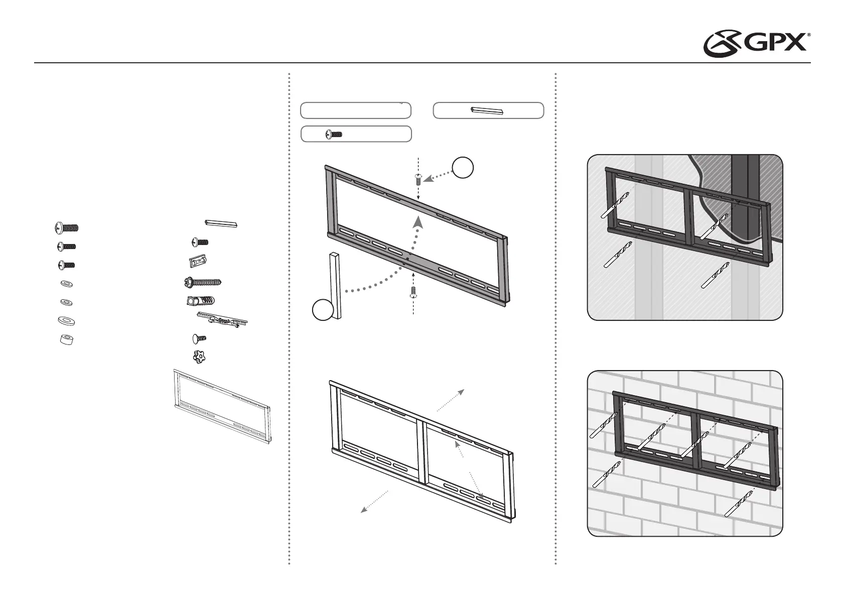
Flad panel støtte
TM35B=
| Mærke: | GPX |
| Kategori: | Flad panel støtte |
| Model: | TM35B= |
Har du brug for hjælp?
Hvis du har brug for hjælp til GPX TM35B= stil et spørgsmål nedenfor, og andre brugere vil svare dig
Flad panel støtte GPX Manualer
3 September 2024

2 September 2024

2 September 2024
Flad panel støtte Manualer
- BlueBuilt
- NEC
- StarTech.com
- Proaim
- Tripp Lite
- Chief
- Metronic
- Ergotron
- Alogic
- Vision
- Equip
- Techly
- Silverstone
- Da-Lite
- Ultimate
Nyeste Flad panel støtte Manualer
3 April 2025
3 April 2025
3 April 2025
2 April 2025

2 April 2025
2 April 2025
2 April 2025
2 April 2025

2 April 2025
2 April 2025