GT613UKRev02.p65
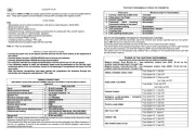
GT613 - 614 - 615 FITTING INSTRUCTIONS
GREY/BLACK
BATTERY
IGNITION KEY
RED
YELLOW/BLACK (RELAY OUTPUT)
+15/54
IGNITION SWITCHED LIVE
YELLOW
CUT
15 AMP FUSE
BROWN
EARTH
VEHICLE
RED/GREY
PINK
GREEN/BLACK
GREEN
GREEN/BROWN
ORANGE
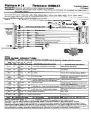
Positive output when the
Additional sensors/modules
To the GREEN/BLACK wire
NEGATIVE command for the starter
PIN SWITCH
BOOT/BONNET ORIGINAL DOOR
PINSWITCH
Connect to either near side or
off side indicator wire
Constant or intermittent output when the alarm is
being triggered (current max. 5A). With this wire it
is possible to drive the HORN relay, an electronic
siren (GT43) the parking lights or a after market satellite
system.
CONTROL UNIT
Connect to positive or negative depending on the
polarity required on the YELLOW/BLACK wire.
immobilisation (current max 80mA)
Additional relay 85
86
87
87A
30
M
Diode 1N4007
+15/54
* NOTE: it is possible to use the GT465 module
RED
BLACK
BLACK (RELAY COMMON)
CHECK LED
+12V
GT431
-+
BROWN
PINK
GREEN/BLACK
GT632GT431
alarm is armed
(current max. 80mA)
on additional sensors/modules
+12V
STARTER MOTOR*
clockwise = more sensitive
anti-clockwise = less sensitive
(use the supplied screwdriver)
WHITE RED
or satellite system
INDICATORS
IMMOBILISATION
CORRECT
ABOVE THE DASHBOARD INCORRECT POSITIONS
CENTRE
DASHBOARD
POSITIONS CONSOLE
RED
WHITE
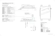
POSITIONING OF THE
GT431 ULTRASONIC SENSORS POSITIONING OF THE GT 632
HYPERFREQUENCY SENSOR
WARNING: Incorrect installation will
increase the risk of water ingress
into the siren.
Make sure that the loom cover is
attached with supplied screws and
the sheath covers the neck of the
loom cover and secured with a cable
tie.
TRANSMITTING
SIDE
LED
ADJUSTMENT
ADJUSTMENT
GT431
-+
SENSITIVITY
ADJUSTMENT
It is advisable to place the alarm as
indicated in the figure to obtain the
maximum of performances by the
shock sensor. Note that the maximum
sensitivity is obtained with a 30°
angulation.
Correct alarm positioning for the shock sensor
MINIMUM SENSITIVITY
SHOCK SENSOR M
AXIMUM SENSIITIVITY
70 degrees