EN50131-2-2:2008
EN50131-1:2006+A1:2009
Environmental Class (EC) II
Security Grade (SG) 2
DS-PD2-P10P-W
Wireless 10m Pet Immune PIR Detector
DS-PWA32-H
Wireless Security Control Panel
A
BC
CEILINGBRACKET
<24kg
2m1m 3m 4m 5m 6m 7m 8m 9m
9m
8m
7m
6m
5m
4m
3m
2m
1m
10m
10m
8m 9m
10m
2.4m
2m1m 3m 4m 5m 6m 7m
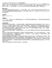
HORIZONTAL COVERAGE
VERTICAL COVERAGE
85
56 ZONES
6 PLANES
°
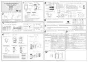
Diagram References
The baeries supplied have been chosen to provide long service life
whilst, for safety reasons, having limited output current.The baery is
protected on purchase by a piece of plasc that must be removed for
operaon. When disposing of the product, the baery must be removed
and disposed of separately in accordance with the local regulaons.
Specification
Battery Information
Hangzhou Hikvision Digital Technology CO.,Ltd. No.555 Qianmo Road, Binjiang District, Hangzhou 310052, China
This and product - if - applicable the supplied accessories too are
m w C and c tarked ith " E" omply herefore w e applicable hith th armonized
Eu tropean s andards listed under the RE Direcve 2014/53/EU,
the RoHS Direcve 2011/65/EU.
For electrical products sold within the European
Community. At the end of the electrical products
lif , it should not be disposed of with household e
waste. Please recycle where facilies exist. Check
with your local Authority or retailer for recycling
advice in your c untry.o
+
-
>5s
+
-
REGISTRATION
+
-
<24kg
>24kg
5s
+
-
LED ON LED OFF
LOW
HIGH
+
+
+
+
+
+
+
+
CR123A
LITHIUM -
HIGH
LOW
TAMPER =
=
REGISTRATION
BRACKET TAMPER
SEE SECTION4
A
B
EC
D
WALLBRACKET
Add Locally
1. Make the security control panel enter the registraon mode.
2.Add the detector: Hold the registraon key unl the three LEDs flash
alternately.The green LED will flash 8 mes if the registraon is finished.
3. Communicaon Test: Release the TAMPER spring to trigger the alarm.
Note: The distance between the security control panel and the detector
should be less than 50 cm.
Initialize the Detector
1.Remove the baery to power the detector off.
2. 5s later,hold the registraon key and reinstall the baery to power the
detector on at the same me to make the three LEDs start flashing alternately.
Release the registraon key while the three LEDs flash once together.
REAR TAMPER
BREAK-OUT
1
3
2
12
3
4
Diagnoscs(Check Signal Strength Before Mounng)
Wireless device control
Please register the detector within 90 seconds aer it being powered on.
3
Brackets Wiring
4
1
2Registraon
E N G L I S H
Diagram References
E N G L I S H 21 23
2
42
52
6
Tear off
Cable Pipe
Cable Pipe
Cable Pipe Cable Pipe
Detec on Zones 56 zones and 6 lanes p
Detec on S peed 0.3–3.0 m/s
Blue Wave Technology Supported
Digital Temperature
Compensa on
Supported
Tam er Protec onp
ront, rear, and bracket tamper
Signal Strength Indicators (SSI) Supported
Range in o en s ace 800mp p
3V lithium ba ery included 1 CR123A x
General ba ery li e (years) 2 f
-10°C to +40°C (Cer ed)fi
Dimensions(H W D) 117 69 50mmx x x x
Lens characteris cs
Key features
Other details
Accessories
Electrical speci ca onsfi
Wireless
Make sure the LED keeps green at the installaon posion when the detector is in
the signal strength mode before mounng.
2122232425
26
27
28
29
210
211
212
2
2
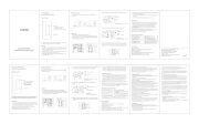
Appearance
Installaon
Set up via APP
Log Into the Web Client
Set Up
1
2
3
Set up via Web Client
AC Power Power On
System Fault
No Fault
Panel is added to
Hik-connect account
Panel is not added to
Hik-connect account
Armed
Disarmed
Alarm Occurred
Device Tampered
No Alarm
Power Off
Fault
Link
Arm
/Disarm
Alarm
Note: Remove the rear cover, and some of the components and interfaces are on the rear panel.
21
22
23
2
5
24
1. Loosen the screw on the rear cover. Slide down the rear cover and remove it from the
control panel.
2. Insert a SIM card into the SIM card slot.
3. Connect the baery to the control panel.
4. Connect the power adapter to the control panel and a power outlet. The power indicator
turns green about 30s later, which means that the device is powered on.
Note: The condion of no SIM card, no baery, AC power off, or network disconnected, will cause Control Panel Fault.
5. Connect the Ethernet cable to an internet outlet. While the device is added to a Hik-Connect
account, the link indicator turns green.
6. Secure the rear cover in the installaon posion with the supplied screws. Aach the
control panel on the rear cover, and ghten the rear cover screw to complete the installaon.
Side Opening
If you need to route the cable though the boon of the panel, remove the sheet of the side
opening.
1. Log into the App Store or Google Play and input Hik-Connect to search and install the
mobile client.
2. Log into the APP with Hi-Connect account.
3. Tap Add Device. Scan the device QR code on the rear panel(on the lable).
4. Tap Connect to a Network. Select Wireless Connecon (AP) as the connecon mode.
5. Push the AP/STA mode switch to the AP posion, tab Confirm.
6. Tap Connect to Wi-Fi on the promt-up window. Select and connect to a stable Wi-Fi , and
click Next.
7. Create a password to acvate the device.
8. Push the AP/STA mode switch to the STA posion.
Note: You need to enter the Verificaon Code (on the device lable which is pasted on the rear panel) before
acvaon if you add the device by entering the device serial No.(SN).
SIM Card Slot
Baery Connector
Network Interface
Power Interface
Reset Buon
AP&STA Switch
Tamper Spring
212
211
2
10
29
28
27
26
Note: The funcon of GPRS or 3/4G(implemented with build-in SIM card slot) depends on the model of the device.
TAMPER Screw
It is compulsory to secure the TAMPER screw.
Specification
Interac onAudio Out ut 1, 1.5Wp
RF Frequency 433 868 Hz/M
RF Distance 800m O en Area(p)
Wired Network Ethernet 10 100M/ M f p Sel -ada ve
Cellular Network GPRS, 3 4G/
u orts re ort ush-no ca on to ARC & Cloud, te t pp p p fi x
o ca on via S S, and audio no ca on via hone callfi M fi p
A lica on iV S-4200, and mobile APPpp M
Protocol SIA - Contact ID
User User 13 (1 Installer, 1 Administrator, and 11 General User)
Consum on (without HDD) <5.6Wp
O era on Tem erature –10 to 55p p ℃ ℃
O era on Humidity 10% to 90%p
Dimension(W H D) 155 155 35mmx x x x
Wireless Device
Connec on
RF
Wi-Fi
Others
4
222
7
Add Peripheral Device
While the control panel is not in the configuraon mode, press the funcon buon on the
side of the control panel once and trigger a peripheral device.
Check RF Signal
While the control panel is not in the configuraon mode, double press the funcon buon,
and you can check the RF signal strength on the peripheral device .
Set up via 4200 Client
Add a Camera for the Zone
Configure Video-Push
1. Download and install the iVMS-4200 client.
Note: Get the client soware from the official website:www.hikvision.com.
2. Enter Device Management page, select the device in the Online Device List, click Edit
Network Sengs, change the port as 80, and click Add to Client.
Note: You should acvate the device for the first usage.
1. Click System-Network Camera, and you can add two cameras for the control panel.
2. Click Wireless Device-Zone, select a zone, click the Sengs icon, and select a camera to link
with the zone.
You can also link a camera with the zone via APP, refer to the Wireless Security Control Panel
User Manual for details.
Funcon Buon Operaon
Input the device IP address in the address bar of the web browser. Create a password to
acvate the device and log into the web client.
Default IP Address when using mobile broswer in the AP mode:192.168.8.1. The device must be in the AP mode.
Default IP Address when connecing the network cable with computer directly :192.0.0.64
Note: Keyfobs cannot be added by funcon buon operaon.
You can view the alarm video via APP and email. For detailed sengs, refer to Security
Control Panel User Manual.
4
For mul-language switch , refer to Security Control Panel User Manual (scan the QR code) for details.
Note: Add card or keyfob via the web client before adding peripheral device for clearing tampering alarm.
CAUTION
RISK OF EXPLOSION IF BATTERY IS
REPLACED BY AN INCORRECT TYPE
DISPOSE OF USED BATTERIES
ACCORDING TO THE INSTRUCTIONS
This product and - if applicable - the supplied accessories too
are marked with "CE" and comply therefore with the
applicable harmonized European standards listed under the RE
Direcve 2014/53/EU, the EMC Direcve 2014/30/EU, the LVD
Direcve 2014/35/EU, the RoHS Direcve 2011/65/EU
2012/19/EU (WEEE direcve): Products marked with this
symbol cannot be disposed of as unsorted municipal waste in
the European Union. For proper recycling, return this product
to your local supplier upon the purchase of equivalent new
equipment, or dispose of it at designated collecon points. For
more informaon see: www.recyclethis.info
2006/66/EC (baery direcve): This product contains a
baery that cannot be disposed of as unsorted municipal
waste in the European Union. See the product documentaon
for specific baery informaon. The baery is marked with
this symbol, which may include leering to indicate cadmium
(Cd), lead (Pb), or mercury (Hg). For proper recycling, return
the baery to your supplier or to a designated collecon
point. For more informaon see:www.recyclethis.info
Recommended Power Adaper
Manufactory: Shenzhen HONOR Electronic Co., Ltd
Model: ADS-12B-06 05010E
Input rang: 100-240V~50/60Hz Max. 0.3A
Output rang: 5V 2.0A
UD13151B-A