Hikvision DS-PWA32-NST Manual

Hikvision Smart hjem DS-PWA32-NST

Læs gratis den danske manual til Hikvision DS-PWA32-NST (4 sider) i kategorien Smart hjem. Denne vejledning er vurderet som hjælpsom af 42 personer og har en gennemsnitlig bedømmelse på 4.5 stjerner ud af 21.5 anmeldelser. Har du et spørgsmål om Hikvision DS-PWA32-NST, eller vil du spørge andre brugere om produktet?

Side 1/4
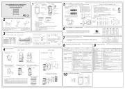
E -2- 8N50131 2:200
E - + 9N50131 1:2006 A1:200
En ro ntal Cl s (EC) IIvi nme as
Sec rit SGu y Gra de ( ) 2
DS-PD2-P10P-W
Wi eles 10 mmun PI ecr s m Pet I e R Det tor
DS-PWA32-HR
Wi eles Securi Co aner s ty ntrol P l UD11755B
A
BC
CEILINGBRACKET
<24kg
2m1m 3m 4m 5m 6m 7m 8m 9m
9m
8m
7m
6m
5m
4m
3m
2m
1m
10m
10m
8m 9m
10m
2.4m
2m1m 3m 4m 5m 6m 7m
HORIZONTAL COVERAGE
VERTICAL COVERAGE
85
56 ZONES
6 PLANES
°
Diag Refe enceram r s
S i npec ficatio
Batter Infor aty m ion
H zhou H sion D tal T ogy CO Ltd. 5 o Road, jiang Dis , H zhou , C naang ikvi igi echnol ., No.55 Qianm Bin trict ang 310052 hi
Thi oduc an appli bl th upplie cce ories pr t d - if ca e - e s d a ss s too are
m ked w h "CE" and c y t refore with the c e ha zed ar it ompl he appli abl rmoni
Eur n st ards listed undopea and EU.
For cal pr s s d n e r n electri oduct ol withi th Eu opea
C y. At e d of e cal pr s ommunit th en th electri oduct
li houl no di po wit hou eholfe, it s d t be s sed of h s d
wit ou lo Authorit aile ec clinh y r cal y or ret r for r y g
advic oue in y r country.
+
-
>5s
+
-
RE STRA ONGI TI
+
-
<24kg
>24kg
5s
+
-
LED ON LED OFF
LOW
HIGH
+
+
+
+
+
+
+
+
CR123A
LITHIUM -
HIGH
LOW
TAMPER =
=
REGISTRATION
BRACKET TAMPER
SEE SECTION4
A
B
EC
D
WALLBRACKET
Add Locally
Note: Th anc ee th ecurit pane the dist e betw n e s y control l d an e r det toec
sho d be ss n 50 .ul le tha cm
REAR T ERAMP
BREAK UT-O
1
34
2
1
3
4
(Check Signal Strength Before
Bracket Wiring
Wireless device control
3
4
1
2
E L HN G I S
Diag Refe enceram r s
E L HN G I S
22 23 24 25
Tear off
Cable Pipe
Cable Pipe
Cable Pipe Cable Pipe
222
7
Detec on Range 10m
Detec on Angle 85°
Detec on Zones 56 zones and 6 planes
Detec on Speed 0.3–3.0 m/s
Moun ng Height 1.8-2.4m
Animal Immunity 24kg
Blue Wave Technology Supported
Digital Temperature
Compensa on
Supported
Tamper Protec on
Front, rear, and bracket tamper
signal input
Signal Strength Indicators (SSI) Supported
Frequency 868MHz
Modula on
2GFSK
Range in open space 800m
3V lithium ba ery included 1x CR123A
General ba ery life (years) 2
Opera ng | storage
-10°C to +40°C (Cer ed)
Weight 125g
Dimensions(H x W x D) 117 x 69 x 50mm
Ceiling Mounted Bracket
Supported
Wall Mounted Bracket
Supported
Lens characteris cs
Key features
Other details
Accessories
Electrical speci caons
Wireless
2
21
2122232425
26
27
28
29
210
211
212
2
2
Appearance
Set up via APP
Log Into the Web Client
Set Up
1
2
3
Set up via Web Client
AC Power Power On
System Fault
No Fault
Panel is added to
Hik-connect account
Panel is not added to
Hik-connect account
Armed
Disarmed
Alarm Occurred
Device Tampered
No Alarm
Power Off
Fault
Link
Arm
/Disarm
Alarm
Note: Remove the rear cover, and some of the components and interfaces are on the rear panel.
21
22
23
25
24
1. Loosen the screw on the rear cover. Slide down the rear cover and remove it from the
control panel.
2. Insert a SIM card i o the SIM card slot. nt
3.
4. Connect the power adapter to the control panel and a power outlet. The power indic or at
turns green about 30s later, which means that the device is powered on.
5. Connect the Ethernet cable to an internet outlet. While the device is added to a Hik-Connect
account, the link indic or turns green. at
6.
Side Opening
opening.
1. Log into the App Store or Google Play and input Hik-Connect to search and install the
mobile client.
2. Log into the APP with Hi-Connect account.
3. Tap Add Device. Scan the device QR code on the rear panel(on the lable).
6. Tap Connect to Wi-Fi on the promt-up window. Select and connect to a stable Wi-Fi , and
click Next.
SIM Card Slot
Network Interface
Power I erfacent
AP&STA Switch
Tamper Spring
212
211
210
29
28
2
7
26
TAMPER Screw
It is compulsory to secure the TAMPER screw.
S i npec ficatio
Alarm Input 32
Alarm Output 32
Siren 2
Keyfob 8
Par on 1
Interac on Audio Output 1, 1.5W
RF Frequency 868MHz
RF Modul a on 2GFSK
RF Distance 800m Open Area( )
Wired Network Ethernet 10M/100M Self-adap ve
Cellular Network GPRS, 3/4G
Supports report push-no ca on to ARC & Clo ud, text
n
o ca on via SMS, and audio no ca on via phone callfi fi
Standard 802.11b/g/n
Encryp on Supported
Chann el 2.4G
Applica on iVMS-4200, and mobile APP
Protocol SIA - Contact ID
IC Card 12
User 13 (1 Installer, 1 Ad ministrator, and 11 General User)
Power 5 VDC 10W
Consump on (without HDD) <5.6W
Opera on Temperature –10 to 55℃ ℃
Opera on Humid ity 10% to 90%
Shell Material PC+ABS
Dimension(WxHxD) 155 x155x35mm
Wireless Device
Connec on
Applica on &
Protocol
User
RF
Others
Wi-Fi
Add Peripheral Device
side of the control panel once and trigger a peripheral device.
Check RF Signal
and you can check the RF signal strength on the peripheral device .
Set up via 4200 Client
Add a Camera for the Zone
Con re Video-Pushfigu
1. Download and install the iVMS-4200 client.
2. Enter Device Management page, select the device in the Online Device List, click Edit
1. Click System-Network Camera, and you can add two cameras for the control panel.
with the zone.
You can also link a camera with the zone via APP, refer to the Wireless Security Control Panel
User Manual for details.
Input the device IP address in the address bar of the web browser. Create a password to
Default IP Address when using mobile broswer in the AP mode:192.168.8.1. The device must be in the AP mode.
You can view the alarm video via APP and email. For detailed
Control Panel User Manual.
4
Note: Add card or keyfob via the web client before adding peripheral device for clearing tampering alarm.
Spacers available if required: SPACER-WE and SPACERBROWN-WE
For electrical products sold within the European Community. At the end of the electrical products life, it
should not be disposed of with household waste. Please recycle where facilies exist. Check with your
Local Authority or retailer for recycling advice in your country.
To prevent possible damage to components, any stac charge on your body needs to be eliminated
before touching the inside of the unit. This can be accomplished by touching some grounded/earthed
metallic conductor such as a radiator/pipework immediately before replacing the baeries.
The baeries supplied have been chosen to provide long service life whilst, for
safety reasons, having limited output current.
The baery is protected on purchase by a piece of plasc that must be
removed for operaon. f Wh is inen d pos g o the uct, th prod e a b ery be must
removed nd dis se ate cc an he a po d of separ ly in a ord c h te wit lo egula .cal r ons
REGISTRATION
LEDs
LEDs
300s
5s
No. 6.
Pan Head
Screw
10m
>10m
< 50CM
Diagram References
E N G L I S H
DS-PD1-MC-WWS
Wireless Magnec Contact
Diagram References
E N G L I S H
2
1
Control Panel x 1
Baery x 1
Magnec Door Contact x 1 Detector x 1
Power Adapter x 1 Screw x 4
IC Card in Special Shapes x 5
Quick Start Guide x1
2
Magnet Detection Performance
Battery Information
Product Warning Information
21
COPYRIGHT ©2018 Hangzhou Hikvision Digital Technology Co., Ltd.
ALL RIGHTS RESERVED.
Any and all informaon, including, among others, wordings, pictures, graphs are the
properes of Hangzhou Hikvision Digital Technology Co., Ltd. or its subsidiaries
(hereinaer referred to be “Hikvision”). This user manual (hereinaer referred to be “the
Manual”) cannot be reproduced, changed, translated, or distributed, parally or wholly,
by any means, without the prior wrien permission of Hikvision. Unless otherwise
spulated, Hikvision does not make any warranes, guarantees or representaons,
express or implied, regarding to the Manual.
About this Manual
This Manual is applicable to the Axiom Security Control Panel Kit.
The Manual includes instrucons for using and managing the product. Pictures, charts,
images and all other informaon hereinaer are for descripon and explanaon only. The
informaon contained in the Manual is subject to change, without noce, due to firmware
updates or other reasons. Please find the latest version in the company website
(hp://overseas.hikvision.com/en/).
Please use this user manual under the guidance of professionals.
Trademarks Acknowledgement and other Hikvision’s trademarks and
logos are the properes of Hikvision in various jurisdicons. Other trademarks and logos
menoned below are the properes of their respecve owners.
ComponentsProduct Informaon
EN50131-2-6:2008
EN50131-5-3:2005+A1:2008
Security Grade (SG) 2
Environmental Class (EC) II
Installaon Notes
Installaon Surfaces
Programming Menus Required
WIRELESS DEVICE CONTROL (REGISTER WIRELESS DEVICE)
DIAGNOSTICS
The contact can be mounted on typical building materials; such as wood, PVC,
brick or metal etc.
It is recommended the contact is learned at the control panel. A signal strength
test should then be performed to make sure the most suitable locaon is chosen,
ensuring opmum wireless range.
Register Locally
1. Make the security control panel enter the registraon mode.
2. Register the detector: Hold the learnt key unl the three LEDs flash
alternately. The green LED will flash 8 mes if the registraon is finished.
3. Communicaon Test: Release the TAMPER spring to trigger the alarm .
Note: The distance between the security control panel and the detector should
be less than 50 cm.
Inialize the Detector
1. Remove the baery to power the detector off.
2. 5s later, hold the registraon key and reinstall the baery to power the
detector on at the same me to make the three LEDs start flashing
alternately. Release the registraon key while the three LEDs flash once
together.
1
2
Specification
Frequency 868MHz
Modula on 2GFSK
Method Fully encrypted rolling code
Ty e 3.0V CR123Ap
Threshold 2.5V + - 5% at 25°C/
Li e to 2 yearsf Up
Colour and Casing White. 2mm ABS
Indica on
LEDs (Signal, Ba ery, Alarm,
Tam er)p
Temperature -10°C to 40°C (Cer ed)fi
Dimensions (H W D)x x
Sensor:27 104 25mm.x x
Magnet: 14 49 16mmx x
Wireless
Ba ery
Materials and Environment
Make sure the LED keeps green at the installaon posion when the detector is in
the signal strength mode before mounng.


Produkt Specifikationer

Mærke: Hikvision
Kategori: Smart hjem
Model: DS-PWA32-NST
Produktfarve: Hvid
USB-port: Ingen
Ethernet LAN-porte (RJ-45): 1
Ethernet LAN: Ja
Wi-Fi-standarder: 802.11b, 802.11g
Strømforbrug (maks.): 10 W
Driftsfrekvens: 868 Mhz
Bevægelsessensor: Ja
Opdagelsesafstand: 10 m
Dør-/vinduessensor: Ja
Sirene: Ingen
Central kontrolenhed tilslutningsmulighedsteknologi: Wi-Fi
Wi-Fi (central kontrolenhed): Ja
Overvågningskamera: Ingen
Central kontrolenhed driftstemperatur (T-T): -10 - 55 °C
Dør/vindue sensor batteritype: CR123A
Dør-/vinduesensor batterispænding: 3 V
Dør/vindue sensor driftstemperatur (T-T): -10 - 40 °C
Dør/vindue sensor dimensioner (BxDxH): 104 x 25 x 27 mm
Central styring opererer med relativ luftfugtighed (H-H): 10 - 90 %
Central kontrolenhed dimensioner (BxDxH): 155 x 35 x 155 mm
PIR detektor: Ja
Dør/vindue sensorgrænseflade: RF trådløst
Central kontrolenhed grænseflade: RF trådløst
Central kontrolenhed batterispænding: 3.8 V
Indbygget backup batteri: Ja

Har du brug for hjælp?

Hvis du har brug for hjælp til Hikvision DS-PWA32-NST stil et spørgsmål nedenfor, og andre brugere vil svare dig