HP Hoffman G28 Manual
Læs gratis den danske manual til HP Hoffman G28 (40 sider) i kategorien Varmeapparat. Denne vejledning er vurderet som hjælpsom af 25 personer og har en gennemsnitlig bedømmelse på 4.7 stjerner ud af 13 anmeldelser.
Har du et spørgsmål om HP Hoffman G28, eller vil du spørge andre brugere om produktet?

Produkt Specifikationer
| Mærke: | HP |
| Kategori: | Varmeapparat |
| Model: | Hoffman G28 |
| Kode for international beskyttelse (IP): | IP56 |
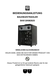
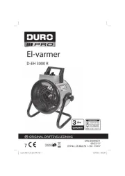
| Type: | Blæser med elektrisk områdevarmer |
| Tænd-/slukkontakt: | Ja |
| Justerbar termostat: | Ja |
| Varmeevne: | 1435 W |
| Varmestrøm (min.): | - W |
| Vekselstrømsindgangsspænding: | 100-120 V |
| Bredde: | 431 mm |
| Dybde: | 256.5 mm |
| Højde: | 725 mm |
| Vægt: | 38101 g |
| Brugervejledning: | Ja |
| Velegnet til: | Indendørs |
| Placeringsmuligheder: | Gulv |
| Produktfarve: | Grå |
| Kontroltype: | Knapper |
| Husmateriale: | Plast |
| Temperatur (maks): | 55 °C |
| Bærbar: | Ja |
| Temperatur (min.): | -8 °C |
| Maksimal kapacitet: | 4900 BUT/t |
Har du brug for hjælp?
Hvis du har brug for hjælp til HP Hoffman G28 stil et spørgsmål nedenfor, og andre brugere vil svare dig
Varmeapparat HP Manualer

Varmeapparat Manualer
- Fluval
- MO-EL
- InfraNomic
- Blaze
- NEO Tools
- Hanover
- Chauvet
- Prismate
- Whirlpool
- Haverland
- Everdure
- Sogo
- PAX
- Excelair
- Camry
Nyeste Varmeapparat Manualer