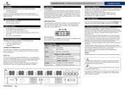
Icom IC-F6122D Manual


Læs gratis den danske manual til Icom IC-F6122D (2 sider) i kategorien Ikke kategoriseret. Denne vejledning er vurderet som hjælpsom af 3 personer og har en gennemsnitlig bedømmelse på 3.7 stjerner ud af 2 anmeldelser. Har du et spørgsmål om Icom IC-F6122D, eller vil du spørge andre brugere om produktet?

Side 1/2
PRECAUTIONS
RWARNING! NEVER
connect the transceiver to an AC
outlet. This may pose a re hazard or result in an electric shock.
RWARNING! NEVER connect the transceiver to a power
source of more than 16 V DC such as a 24 V battery. This
could cause a re or damage the transceiver.
RWARNING! NEVER cut the DC power cable between
made after cutting, the transceiver might be damaged.
RWARNING! NEVER place the transceiver where normal
operation of the vehicle may be hindered or where it could
cause bodily injury.
RWARNING! NEVER operate the transceiver during a
lightning storm. It may result in an electric shock, cause
a re or damage the transceiver. Always disconnect the
power source and antenna before a storm.
CAUTION: DO NOT allow children to touch the
transceiver. Place the transceiver in a secure place to
avoid inadvertent use by unauthorized persons.
CAUTION: DO NOT expose the transceiver to rain, snow
or any liquids.
CAUTION: DO NOT use the non-specied microphone.
Other microphones have different pin assignments and
may damage the transceiver.
CAUTION: DO NOT use or place the transceiver in areas
with temperatures below –25°C or above +55°C, or in
areas subject to direct sunlight, such as the dashboard.
CAUTION: DO NOT operate the transceiver without
running the vehicle’s engine. The vehicle’s battery will
quickly run out when the transceiver transmits while the
vehicle’s engine is OFF.
CAUTION: DO NOT place the transceiver in excessively
dusty environments.
CAUTION: DO NOT place the transceiver against walls.
This will obstruct heat dissipation.
CAUTION: DO NOT use harsh solvents such as benzine
or alcohol when cleaning, as they will damage the
transceiver surfaces.
NEVER place the transceiver in an insecure place to avoid
inadvertent use by unauthorized persons.
BE CAREFUL! The transceiver will become hot when
operating continuously for long periods of time.
Icom is not responsible for the destruction, damage to, or
performance of any Icom or non-Icom equipment, if the
malfunction is because of:
Force majeure, including, but not limited to, res,
earthquakes, storms, oods, lightning, other natural
disasters, disturbances, riots, war, or radioactive
contamination.
The use of Icom transceivers with any equipment that is
not manufactured or approved by Icom.
VOICE CODING TECHNOLOGY
The AMBE+2™ voice coding Technology embodied in this
product is protected by intellectual property rights including
patent rights, copyrights and trade secrets of Digital Voice
Systems, Inc. This voice coding Technology is licensed
solely for use within this Communications Equipment.
The user of this Technology is explicitly prohibited from
attempting to extract, remove, decompile, reverse
engineer, or disassemble the Object Code, or in any other
way convert the Object Code into a human-readable form.
U.S. Patent Nos.
#8,595,002, #8,359,197, #8,315,860, #8,200,497,
#7,970,606, #6,912,495 B2.
Icom, Icom Inc. and the Icom logo are registered trademarks
of Icom Incorporated (Japan) in Japan, the United States, the
United Kingdom, Germany, France, Spain, Russia, Australia,
New Zealand, and/or other countries.
dPMR and the dPMR logo are trademarks of the dPMR
MoU Association.
AMBE+2 is a trademark and property of Digital Voice
Systems Inc.
All other products or brands are registered trademarks or
trademarks of their respective holders.
EXPLICIT DEFINITIONS
WORD DEFINITION
RWARNING!
Personal injury, re hazard or electric
shock may occur.
CAUTION Equipment damage may occur.
NOTE
If disregarded, inconvenience only. No
risk of personal injury, re or electric
shock.
IMPORTANT
This instruction sheet includes some functions that are
usable only when they are preset by your dealer. The
transceiver may have other functions and operations that
are not described in this instruction sheet. Ask your dealer
for preset function details.
SUPPLIED ACCESSORIES
Microphone
Microphone hanger
and screw set
Microphone
hanger cable
DC power cable Function name
stickers*
Mounting bracket
Flat washers
Nuts Mounting screws
(5×12)
Bracket bolts Self-tapping screws
(5×20)
Spring washers
* Used for labeling the programmable function keys
according to their assigned functions.
NOTE: Some accessories are not supplied, or the shape
is different, depending on the transceiver version.
OPTIONS
OPC-1939, OPC-2078 ACC CABLE
Enables you to connect to an external terminal.
OPC-1939: D-sub 15-pin, an external level converter
(user supplied) is required.
OPC-2078: D-sub 25-pin, built-in level converter
NOTE:
No Digital Modulation “IN” using accessory cables.
HM-152, HM-152T, HM-148G, HM-148T, HM-211
HAND MICROPHONE
HM-152: Hand microphone
HM-152T:DTMF microphone
HM-148G: Self ground heavy duty microphone
HM-148T: Self ground heavy duty DTMF microphone
HM-211: Noise Canceling microphone
SM-26 DESKTOP MICROPHONE
SP-30, SP-35, SP-35L EXTERNAL SPEAKER
Input impedance: 4 Ω
SP-30: Rated input: 20 W, Maximum input: 30 W
SP-35, SP-35L: Rated input: 5 W, Maximum input: 7 W
ABOUT CE AND DOC
Hereby, Icom Inc. declares that the versions
of IC-F5122D and IC-F6122D which have
the “CE” symbol on the product, comply with
the essential requirements of the Radio
Equipment Directive, 2014/53/EU, and the
restriction of the use of certain hazardous substances in
electrical and electronic equipment Directive, 2011/65/EU.
The full text of the EU declaration of conformity is available
at the following Internet address:
https://www.icomjapan.com/support/
DISPOSAL
The crossed-out wheeled-bin symbol on your
product, literature, or packaging reminds you
that in the European Union, all electrical and
electronic products, batteries, and
accumulators (rechargeable batteries) must
be taken to designated collection locations at
the end of their working life. Do not dispose
of these products as unsorted municipal waste. Dispose of
them according to the laws in your area.
ANTENNA
A key element in the performance of any communication
systems is the antenna. Contact your dealer for
information regarding antennas and how to install them.
FUSE REPLACEMENT
Fuses are installed in the supplied DC power cable. If a
fuse blows, track down the source of the problem, repair it,
and then replace the damaged fuse with a new rated one.
LFuse rating: 250 V 10 A
NOTE: Use only specied fuses.
CLEANING
If the transceiver becomes dusty or dirty, wipe it clean with
a soft, dry cloth.
About E-marking: Detailed installation notes for
Icom mobile transceivers to be tted into vehicles are
available. Please contact your Icom dealer or distributor.
Fuse Coding explanation
Fuse Coding: FUSE 250 V 10 A
Fuse Voltage rating: 250 Volts
Fuse Current rating: 10 Amperes
For European versions
CAUTION: DO NOT Hot surfaces. touch
the transceivers surface after continuously
transmitting for long periods of time. The
transceivers chassis radiates heat, and it
will become hot to protect the power
amplier unit from overheating. Touching it
may cause a burn.
FREQUENCY RANGE AND OUTPUT POWER
Model Version
Frequency
Range
Output
Power
VHF Mobile Transceiver
IC-F5122D
EUR-31
DPM-31
136–174 MHz 25 W
UHF Mobile Transceiver
IC-F6122D
EUR-31
DPM-31
400–470 MHz
25 W
Channel spacing:
6.25 kHz*,
12.5 kHz, 20 kHz, 25 kHz
* Only Digital mode
1-1-32 Kamiminami, Hirano-ku,
Osaka 547-0003, Japan
Oct. 2021
A6906W-1EU-6
Printed in Japan
© 20112021 Icom Inc.
INSTRUCTIONS
Thank you for choosing this Icom product.
READ ALL INSTRUCTIONS carefully and completely
before using this product.
VHF MOBILE TRANSCEIVER
|F5122D
UHF MOBILE TRANSCEIVER
|F6122D
FUNCTION DISPLAY
BASIC OPERATION
1
AF VOLUME CONTROL KNOB [VOL]
Rotate the knob to adjust the audio output level.
LMinimum audio level is preprogrammed.
2UP/DOWN KEYS [CH Up]/[CH Down]
Push to select an operating channel.
LThe desired function can be assigned by your dealer.
3POWER KEY [ ]
Push to turn the transceiver ON or OFF.
LThe following optional functions are available at power
ON:
Automatic scan start
• Password prompt
4
DEALER-PROGRAMMABLE KEYS
Required functions can be independently programmed
by your dealer.
PANEL DESCRIPTION
NOTE: Different functions may have been assigned to the keys by your dealer, except for the Power key.
1 3
4
5
2
Speaker
Function display
5
MICROPHONE CONNECTOR
Connect the supplied or optional microphone.
CAUTION: DO NOT
connect non-specied
microphones. The pin assignments may be different
and may damage the transceiver.
D
Microphone
The supplied or optional microphone has a PTT switch
and a hanger hook.
L
The following functions are available when the microphone
is ON or OFF hook (depending on the preprogramming):
Automatic scan starts when you put it ON hook.
Scan is canceled when you take it OFF hook.
Scan is paused when you take it OFF hook.
Automatically selects the Priority channel when you
take it OFF hook.
Sets to the Inaudible mode (mute state) when you
put it ON hook.
Sets to the Audible mode (unmute state) when you
take it OFF hook.
1
TRANSMIT ICON
Displayed while transmitting a signal.
2
BUSY ICON
Displayed while the channel is busy (receiving).
3
SIGNAL STRENGTH ICON
Displays the relative receive signal strength level.
Receive Signal level
StrongWeak
4
LOW POWER ICON
Displayed when low output power is selected.
5
AUDIBLE ICON
Displayed when the channel is in the Audible
(unmuted) mode.
Displayed when a matching signal is received.
6
COMPANDER/GPS ICON
(Only for the dPMR models)
Displayed when the Compander function is ON, and
the GPS Indicator is set to OFF in the programming
software.
Displayed when the GPS receiver acquires the GPS
signal from a satellite, and the GPS Indicator is set
to ON in the programming software.
7
ENCRYPTION / SCRAMBLER ICON
For the NXDN models:
Displayed when the Encryption function is ON while
operating in the Digital mode.
For the dPMR models:
Displayed when the Voice Scrambler function is ON
while operating in the Digital mode.
8
BELL ICON
Displayed or blinks when a matching signal is
received, depending on the presetting.
9
SCAN ICON
Blinks during a scan.
Displayed when a scan channel is selected.

SCROLL ICON
(Only for the dPMR models)
Displayed when an SDM (Short Data Message),
including more than 8 characters, is selected in the
received message selection mode.

ALPHANUMERIC DISPLAY
Displays an operating channel number, channel name,
User Set mode contents, DTMF code, etc.
REAR PANEL CONNECTION
e
r
Black
Red
q
w
t
1
ANTENNA CONNECTOR
Connect to an antenna. Ask
your dealer about antenna
selection and placement.
4

OPTIONAL CABLE
(OPC-1939, OPC-2078)
Connect an external modem
or dimmer control.
5

DC POWER RECEPTACLE
Connect to a 12 V DC battery. Pay
attention to polarities.
3
MICROPHONE HANGER
Connect the supplied microphone
hanger to the vehicle’s ground
for microphone ON/OFF hook
functions.
2
EXTERNAL SPEAKER JACK
Connect to a 4 ~ 8 Ω external speaker.
Optional speaker
Antenna
12 V
Battery
NOTE:
Use the terminals for the
cable connections.
RWARNING! NEVER remove the
fuse-holders from the DC power cable.
RWARNING! NEVER connect to
a 24 V battery. This could damage
the transceiver.
Crimp
Solder
DReceiving and transmitting
Receiving:
1. Push [CH Up] or [CH Down] to select a channel.
output level to a comfortable listening level.
NOTE:
Depending on the presetting, the transceiver
automatically transmits the microphone audio for the preset
period of time, when a matching RX code signal is received.
Transmitting:
1. Wait for the channel to become clear to avoid
interference.
LThe channel is busy when the busy icon is displayed.
2. Take the microphone OFF from the hook.
The Audible mode is selected.
A priority channel may be automatically selected.
3. Holding down [PTT] to transmit.
4. Release [PTT] to receive.
IMPORTANT: To maximize the readability of your signal
1. Pause briefly after pushing [PTT].
2. Hold the microphone 5 to 10 cm from your mouth, then
speak into the microphone at your normal voice level.
DTurning ON the transceiver
1. Push [ ] to turn ON the transceiver.
2. If the transceiver is preset for a start up password, enter
the digit codes as directed by your dealer.
L The keys shown below can be used for password entry.
The transceiver detects numbers in the same block as
identical.
Therefore “01234” and “56789” are the same.
KEY
NUMBER
0
5
4
9
3
8
2
7
1
6
NOTE:
If the “PASSWORD” indication still displayed after
inputting 6 digits, the input code number may be incorrect.
Turn OFF the transceiver and re-enter your password.
There are several methods to select channels, and they
may differ, depending on the presetting or the transceiver
models.
NON-ZONE TYPE:
To select the desired operating channel:
Push [CH Up] or [CH Down].
Push one of [MR-CH 1] ~ [MR-CH 4].
ZONE TYPE:
To select the desired operating channel:
Push [Zone], then push [CH Up] or [CH Down].
DSelecting a channel
AUTOMATIC SCAN TYPE:
Channel setting is not necessary for this type. When
turning ON the power, the transceiver automatically starts
scanning. Scanning stops when a signal is detected.
VOTING OPERATION for the Zone selection
(Only for the dPMR models)
The transceiver automatically starts scanning when a
zone, specied for the voting operation, is selected.
The voting scan detects the signal of the repeater and
automatically selects the strongest station.
12 3 4 5 6 7 8 9


Produkt Specifikationer

Mærke: Icom
Kategori: Ikke kategoriseret
Model: IC-F6122D

Har du brug for hjælp?

Hvis du har brug for hjælp til Icom IC-F6122D stil et spørgsmål nedenfor, og andre brugere vil svare dig